


 177 / 582

BETA Protecting
Low-Voltage Fuse Systems
3
NW cylindrical fuse systems
3/27
Siemens ET B1 · 10/2008
3
*
You can order this quantity or a multiple thereof.
■
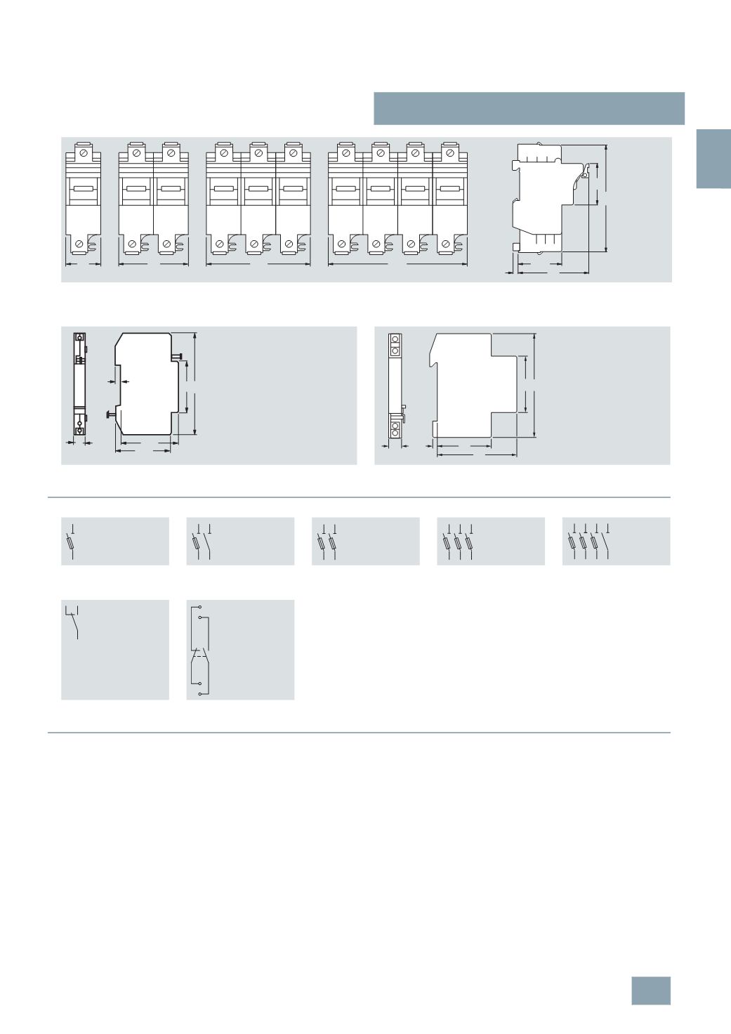
Schematics
■
More information
Installation
Fuse holders, sizes 8 mm × 32 mm and 10 mm × 38 mm have a
sliding catch that enables the removal of individual devices from
the assembly.
The infeed can be from the top or the bottom. Because the
cylindrical fuse holders are fitted with the same anti-slip terminals
at the top and the bottom, the devices can also be bus-mounted
at the top or the bottom.
Auxiliary switches
Auxiliary switches are available for the cylindrical fuse holders.
These are simply clipped onto the base using the factory-fitted
brackets.
Sizes 8 mm × 32 mm and 10 mm × 38 mm:
The auxiliary switches support the remote display of the ON/OFF
switching state of the fuse holder.
Sizes 14 mm × 51 mm and 22 mm × 58 mm:
The auxiliary switches support the remote display of fuse failure.
However, fuse links with strikers are required for this function.
When the fuse is tripped, a small striking pin – the striker – shoots
out of the front of the fuse. Over an armature link in the auxiliary
switch, the kinetic energy of this striker is used to switch a mini
switch, which then initializes this signal over a floating contact.
3
NW7 2
1
P
1
P+N / 2P
3
P
3
P+N
Auxiliary switches
3
NW7 901
3
NW7 902
3
NW7 903
1
P
1
P+N
2
P
3
P
3
P+N
Auxiliary switches
3
NW7 901
3
NW7 902
3
NW7 903
70
43
45
7
117
I2_07869c
144
108
72
36
I2_15459
45
44
6 9
64
83
22 14
13/21
22
12
21
11
© Siemens AG 2008