


 173 / 582

BETA Protecting
Low-Voltage Fuse Systems
3
NW cylindrical fuse systems
3/23
Siemens ET B1 · 10/2008
3
*
You can order this quantity or a multiple thereof.
■
Overview
Cylindrical fuses are standard in Europe. There are a range of
different cylindrical fuse links and holders that comply with the
standards IEC 60269-1, -2 and -3. They are suitable for use in
industrial applications. In South West Europe they are also ap-
proved for use in residential buildings.
The cylindrical fuse holders are also approved to UL 512.
The cylindrical fuse holders are tested and approved as fuse
disconnectors in accordance with the switching device standard
IEC 60947-3. They are not suitable for switching loads.
Cylindrical fuse holders can be supplied with or without signal
detectors. In the case of devices with signal detectors, a small
electronic device with LED is located behind an inspection window
in the plug-in module. If the inserted fuse link is tripped, this is
indicated by the LED flashing
An auxiliary switch, which can be laterally mounted, enables the
forwarding of the switching state of the fuse holder, and thus an
integration of the fuses in the automation processes.
■
Benefits
•
Devices with pole number 1P+N are available in a single modular
width. This reduces the footprint by 50 %.
•
The sliding catch for type ranges 8 x 32 mm and 10 x 38 mm
enables the removal of individual devices from the assembly.
•
Space for a spare fuse in the plug-in module enables the fast
replacement of fuses. This saves time and money and increases
plant availability.
•
A flashing LED signals that a fuse link has been tripped. This
enables fast detection during runtime.
■
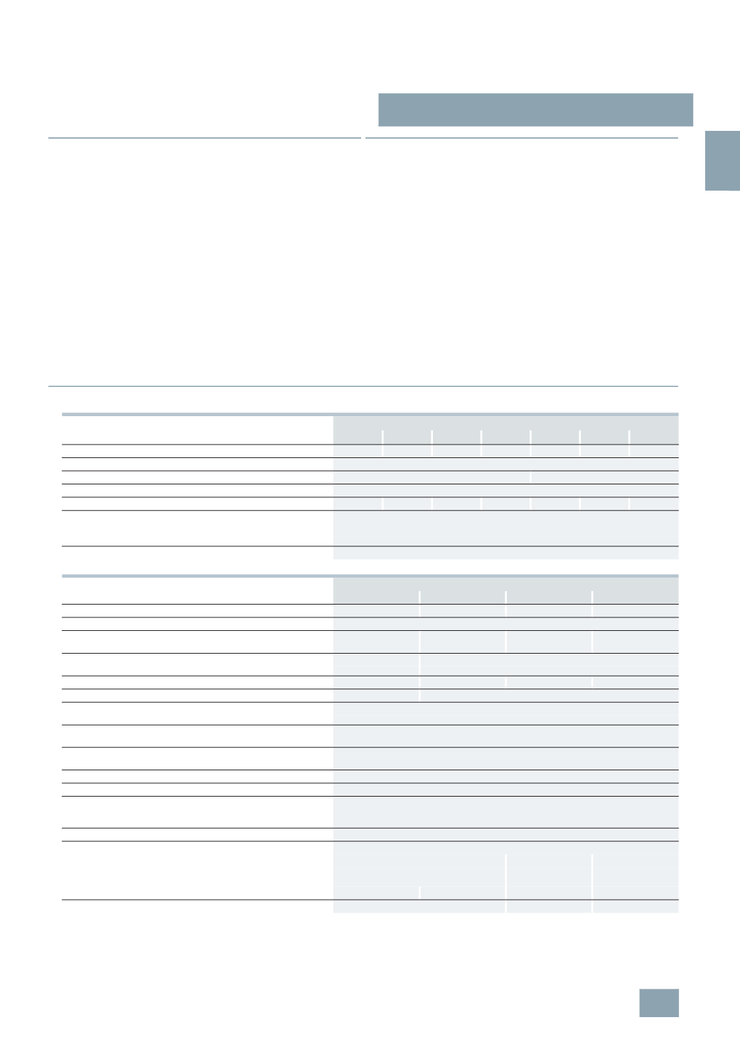
Technical specifications
Cylindrical fuse links
3
NW6 3..
3
NW6 0..
3
NW6 1..
3
NW6 2..
3
NW8 0..
3
NW8 1..
3
NW8 2..
Sizes
mm × mm 8 × 32
10
× 38 14 × 51 22 × 58 10 × 38 14 × 51 22 × 58
Standards
IEC 60269-1, -2, -3; NF C 60-200; NF C 63-210, -211; NBN C 63269-2, CEI 32-4, -12
Operational class
gG
aM
Rated voltages U
n
V AC
400
or 500
Rated current
I
n
A
2 ... 20 2 ... 32 4 ... 50 8 ... 100 0.5 ... 25 2 ... 50 10 ... 100
Rated breaking capacity
• 500
V versions
kA AC 100
• 400
V versions
kA AC 20
Mounting position
Any, but preferably vertical
Cylindrical fuse holders
3
NW7 3..
3
NW7 0..
3
NW7 1..
3
NW7 2..
Sizes
mm × mm 8 × 32
10
× 38
14
× 51
22
× 58
Standards
IEC 60269-1, -2, -3; NF C 60-200, NF C 63-210, -211; NBN C 63269-2-1; CEI 32-4, -12
Certifications
Acc. to UL
--
U
U
--
Acc.
to CSA
--
s
s
--
Rated voltage
U
n
V AC
400
690
Acc. to UL/CSA V AC
400
600
Rated current
I
n
A AC
20
32
50
100
Rated breaking capacity
kA
20
100
Switching capacity
•
Utilization category
AC-20B (switching without load), DC-20B
No-voltage changing
of fuse links
Yes
Sealable
when installed
Yes
Mounting position
Any, but preferably vertical
Degree of protection
Acc. to IEC 60529
IP20, with connected conductors
Terminals
with touch-protection
acc. to BGV A3 at incoming and
outgoing feeder
Yes
Ambient temperature
°C
-5 ...
+40, humidity 90 % at +20
Conductor cross-sections
•
Rigid
mm
2
0.5 ... 10
2.5 ... 10
4 ... 10
•
Stranded
mm
2
0.5 ... 10
2.5 ... 25
4 ... 50
•
Finely stranded, with end sleeve
mm
2
0.5 ... 10
2.5 ... 16
4 ... 35
•
AWG (American wire gauge )
--
10 ... 20
6 ... 10
--
Tightening torques
Nm
1.2
2.0
2.5
© Siemens AG 2008