


 176 / 582

BETA Protecting
Low-Voltage Fuse Systems
3
NW cylindrical fuse systems
3/26
Siemens ET B1 · 10/2008
3
*
You can order this quantity or a multiple thereof.
■
Dimensional drawings
Number of
poles
I
n
For fuse links of
size
MW DT Order No.
Price
per PU
PG PU PS*/
P. unit
Weight
per PU
approx.
A
mm × mm
Unit(s) Unit(s) kg
3
P
20
8
×32
3
A
3
NW7 333
018 1
1
0.172
32
10
× 38
3
}
3
NW7 033
018 1
1/4 0.172
50
14
× 51
4.5
}
3
NW7 131
018 1
1
0.295
100
22
× 58
6
}
3
NW7 231
018 1
1
0.691
3
P+N
20
8
× 32
3
A
3
NW7 363
018 1
1
0.185
32
10
× 38
3
}
3
NW7 063
018 1
1
0.185
50
14
× 51
6
A
3
NW7 161
018 1
1
0.315
100
22
× 58
8
A
3
NW7 261
018 1
1
0.475
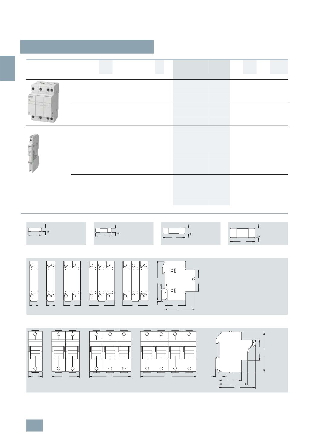
Auxiliary switches
For indicating disconnection of the fuse link,
solely for application of striker fuse links.
For retrofitting using the factory-fitted brackets.
Contact: 250 V AC, 5 A,
Minimum contact load: 12 V, 25 mA
For fuse bases
14
× 51
0.5
B
3
NW7 901
018 1
1
0.050
For fuse bases
22
× 58
B
3
NW7 902
018 1
1
0.050
For indicating the switching state of the fuse
holder. For retrofitting using the factory-fitted
brackets.
Contact: 230 V AC, 6 A/110 V DC, 1 A
Minimum contact load: 12 V, 25 mA
Terminals 1.5 mm² - 0.5 Nm
N
For fuse holders
10
× 38
0.5
B
3
NW7 903
018 1
1
0.034
Sizes
8
× 32 mm
10
× 38 mm
14
× 51 mm
22
× 58 mm
3
NW7 0, 3NW7 3
1
P
1
P+N 2P
3
P
3
P+N
3
NW7 1
1
P
1
P+N / 2P
3
P
3
P+N
31,5
8,5
I2_06702c
38
I2_06703c
10,3
51
14,3
I2_06701c
58
22,2
I2_06704c
55
43
90
45
27
54
81
108
I2_07853b
7
70
© Siemens AG 2008