


 146 / 582

BETA Protecting
Residual Current Protective Devices
Residual-current operated circuit breakers
2/38
Siemens ET B1 · 10/2008
2
*
You can order this quantity or a multiple thereof.
Application
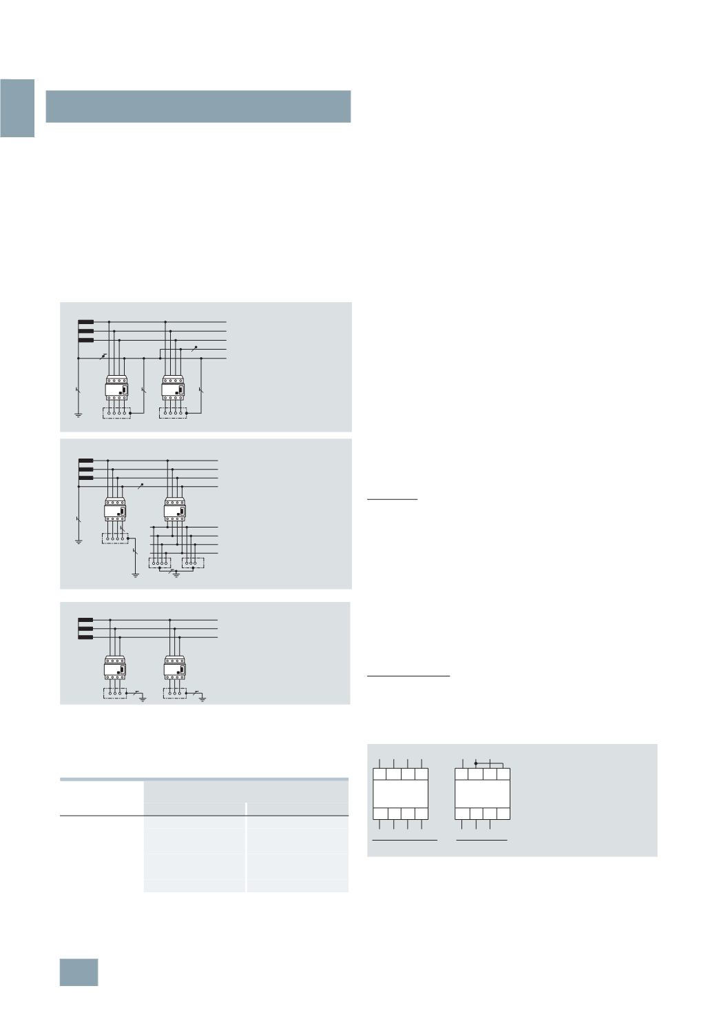
Residual current protective devices can be used in all three system
types (DIN VDE 0100-410).
In the IT system, tripping is not required for the first fault as this
situation cannot produce any dangerous touch voltages. It is
essential that an insulation monitoring device is fitted so that the
first fault is indicated by an acoustic or visual signal and the fault
can be eliminated as quickly as possible. Tripping is not requested
until the 2nd fault. The required compliance with the trip condi-
tions of the TN or TT system will depend on how the device is
grounded. A residual current protective device is also a suitable
circuit-protection device, whereby a separate residual current
protective device is required for each piece of current-using
equipment.
Grounding resistances
When using residual current protective devices in a TT system,
the maximum grounding resistances (as shown in the following
table) must be complied with, depending on the rated residual
current and the max. permissible touch voltage.
Design and method of operation of residual current protective
devices
The design of residual current protective devices is largely
determined by 3 function groups:
1)
Summation current transformers for fault-current detection
2)
Releases to convert the electrical measured quantities into a
mechanical tripping operation
3)
Breaker mechanism with contacts
The summation current transformer covers all conductors required
to conduct the current, i.e. also the neutral conductor where
applicable.
In a fault-free system, the magnetizing effects of the conductors
through which current is flowing cancel each other out for the
summation current transformer as the sum of all currents is zero
(
as defined in Kirchhoff's current law. There is no residual mag-
netic field left that could induce a voltage in the secondary
winding.
However, by contrast, if a residual current is flowing due to an
insulation fault, this destroys the equilibrium and a residual
magnetic field is left in the transformer core. This generates a
voltage in the secondary winding, which then uses the release
and the breaker mechanism to switch off the electrical circuit
afflicted by the insulation fault.
This tripping principle operates independently of the supply voltage
or an auxiliary power supply. This is also a condition for the high
protection level provided by residual current protective devices
according to IEC/EN 61008 (VDE 0664).
This is the only way to ensure that the full protective action of the
residual current protective device is maintained even in the
event of a system fault, e.g. failure of an outer conductor or an
interruption in the neutral conductor.
Test button
All residual current protective devices are equipped with a test
button. Simply press this button to test whether the residual
current protective device is ready to run. Pressing the test button
generates an artificial residual current – the residual current
protective device must trip.
We recommend testing the functionality when commissioning
the system and then at regular intervals – approx. every six
months.
Furthermore, it is also essential to ensure compliance with the
test intervals specified in the pertinent rules and regulations
(
e.g. accident prevention regulations).
The minimum operational voltage for operation of the test equipment
is 100 V AC (series 5SM3)
1)
.
1)
For detailed information, see Technical specifications.
3-
pole connection
4-
pole residual current protective devices can also be operated
in 3-pole systems. In this case, connection must be at terminals
1, 3
and 5 and 2, 4 and 6.
The function of the test equipment is only ensured if a jumper is
fitted between terminals 3 and N.
Rated residual
current
Max. permissible grounding resistance at a
max. permissible touch voltage of
I
n
50
V DC
25
V DC
10
mA
5000
2500
30
mA
1660
830
100
mA
500
250
300
mA
166
83
500
mA
100
50
1
A
50
25
L1
L2
L3
N
PEN
N PE
PE
TN-C
TN-S
TN network
RCCB
RCCB
I2_06153f
L2
L3
N
L1
PE
PE
L2
L3
N
L1
TT network
RCCB
RCCB
I2_06154f
L2
L3
L1
PE
PE
IT network (conditional)
RCCB
RCCB
I2_06155e
1 3 5
N
6
N
2 4
L1 L2 L3 N
1 3 5
N
6
N
2 4
L1 L2 L3
I2_07557a
3
x 230 V AC + N
3
x 400 V AC + N
3
x 230 V AC
3
x 400 V AC
© Siemens AG 2008