


 147 / 582

BETA Protecting
Residual Current Protective Devices
Residual-current operated circuit breakers
2/39
Siemens ET B1 · 10/2008
2
*
You can order this quantity or a multiple thereof.
SIGRES RCCB for harsh environmental conditions
Our SIGRES RCCBs have been developed for use in environments
with increased pollution gas loads, such as
•
Indoor swimming pools: chlorine gas atmosphere,
•
Agriculture: ammoniac,
•
Worksite distribution boards, chemical industry: nitrogen
oxides [NO
x
],
sulfur dioxide [SO
2
]
A significant increase in service life is achieved using our patented
active condensation protection.
When using SIGRES RCCBs, the following points must be observed:
•
The infeed must always be from below, from terminals 2/N or
2/4/6/
N.
•
Before carrying out insulation tests on installation systems with
voltages greater than 500 V, the SIGRES RCCB must be
switched off or the cables on the input side (below) must be
disconnected.
Short-time delayed tripping, super resistant
æ
Electrical loads that temporarily produce high leakage currents
when they are switched on (e.g. temporary residual currents
flowing through interference-suppression capacitors between
outer conductor and PE) may trip instantaneous residual current
protective devices, if the leakage current exceeds the rated
residual current
I
n
of the residual current protective device.
Short-time delayed, super resistant residual current protective
devices can be installed for this type of application, where it is not
possible, or only partially possible, to eliminate such interference
sources. These devices have a minimum tripping delay of 10 ms,
i.e., they should not trip for a residual current pulse of 10 ms. This
complies with the maximum permissible break times according
to IEC/EN 61008-1 (VDE 0664-10). The devices have a high
surge current withstand capability of 3 kA.
Short-time delayed, super resistant residual current protective
devices have the identification code
æ
.
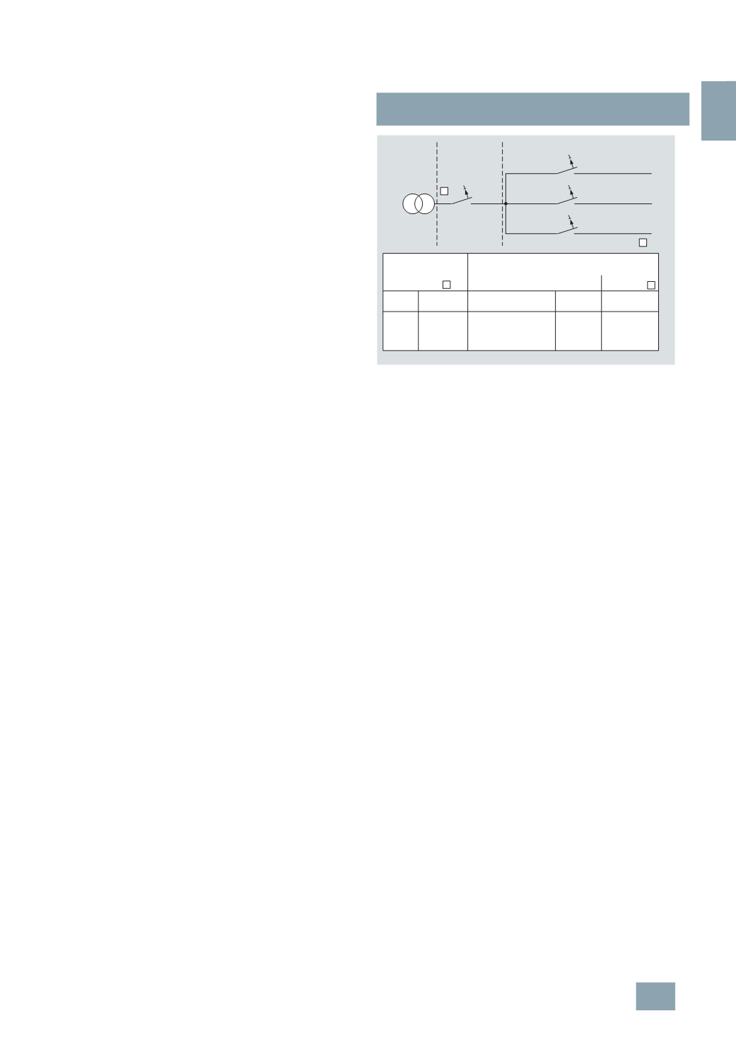
Selective tripping
î
Residual current protective devices normally have an instantaneous
tripping operation. This means that a series connection of this
type of residual current protective devices does not provide
selective tripping in the event of a fault. In order to achieve
selectivity for a series connection of residual current protective
devices, both the tripping time and the rated residual current of
series-connected devices must be time graded. Selective residual
current protective devices have a tripping delay.
Furthermore, selective residual current protective devices must
have an increased surge current withstand capability of at least
3
kA according to IEC/EN 61008-1 (VDE 0664-10). Siemens
devices have a surge current withstand capability of 5 kA.
Selective residual current protective devices have the identification
code
î
.
The table below shows the time grading options available for
residual current protective devices for selective tripping in series
connection with devices without time delay and super resistant
devices with short-time delay
æ
.
1)
For residual current circuit breakers of type AC: < 40 ms.
Versions for 50 … 400 Hz
Due to their principle of operation, the standard versions of residual
current protective devices are designed for maximum efficiency
in 50/60 Hz systems. Product standards and tripping conditions
also refer to this frequency. The sensitivity decreases with
increasing frequency. In order to implement an effective
fault-current protection for applications in systems up to 400 Hz
(
e.g. industry), you need to use suitable devices. This type of
residual current protective devices fulfills the tripping conditions
up to the specified frequency and provides the appropriate level
of protection.
Residual current circuit breaker with left-side N-connection
The fact that the RCCBs are usually located to the left of the
miniature circuit breakers, but have their N wire connection on
the right-hand side, interferes with the integrated busbar connection.
For this reason, when used with miniature circuit breakers, RCCBs
require a special busbar. In order to enable the use of standard
busbars, 4-pole RCCBs are also provided with their N connection
on the left-hand side. This means that it is still possible to install
RCCBs to the left of miniature circuit breakers using standard
busbar connections.
K
K
S
S
100
mA
300
mA
500
mA
1000
mA
50 ...150
ms
≤ 40 ms 20 … 40 ms
I
∆n
I
∆n
I2_15510
10
mA or 30 mA
10
mA, 30 mAor 100 mA
10
mA, 30 mA ,100 mA
300
mA
RCCB
RCCB
RCCB
Main
distribution
board
Selective
version
Sub-distribution board
Instantaneous or super resistant
Downstream RCCB
or
Upstream RCCB
for selective
disconnection
Break time
at 5 x
I
∆n
Break time
at 5 x
I
∆n
Break time
at 5 x
I
∆n
Instantaneous
version
Super resistant
version
RCCB
© Siemens AG 2008