


 141 / 582

BETA Protecting
Residual Current Protective Devices
Busbars
2/33
Siemens ET B1 · 10/2008
2
*
You can order this quantity or a multiple thereof.
■
Selection and ordering data
■
Dimensional drawings
Note:
Pin spacing in MW
Dimensions of side views in mm (approx.).
Version
Pin
spacing
Length DT Order No.
Price
per PU
PG PU PS*/
P. unit
Weight
per PU
approx.
MW mm
Unit(s) Unit(s) kg
5
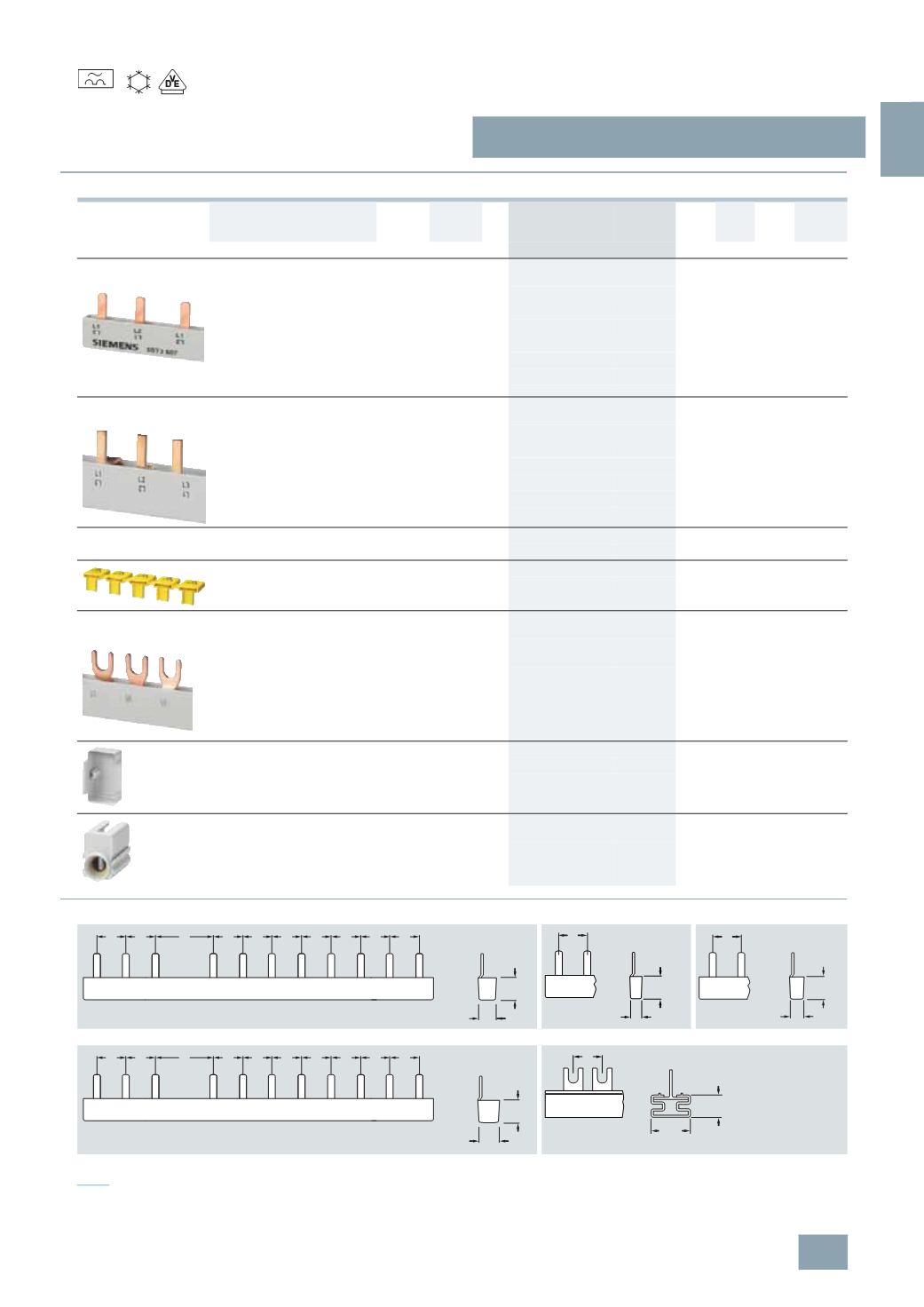
ST3 6 busbar systems, fixed lengths,
cannot be cut, fully insulated
For 1 RCCB 4P, N connection right, and 8 MCB 1P
•
Three-phase 10 mm
2
1
210
A
5
ST3 624
027 1
10 0.075
•
Three-phase 16 mm
2
1
210
A
5
ST3 654
027 1
10 0.114
For 6 RCBOs 1P+N together
•
Two-phase 10 mm
2
210
A
5
ST3 608
027 1
10 0.048
•
Two-phase 16 mm
2
210
A
5
ST3 638
027 1
10 0.076
5
ST3 7 busbar systems, 12 MW,
can be cut, with end caps
For 1 RCCB 4P, N connection right, and 8 MCB 1P
•
Three-phase 16 mm
2
A
5
ST3 717
027 1
25 0.150
For 6 RCBO 1P+N
•
Two-phase 10 mm
2
1
216
A
5
ST3 734
027 1
1
0.060
•
Two-phase 16 mm
2
1
216
A
5
ST3 704
027 1
1
0.060
End caps for 5ST3 7, can be cut
For two-phase busbars
}
5
ST3 750
027 1
10 0.001
Touch protection
For free connections, yellow (RAL 1004)
A
5
ST3 655
027 1
10 0.003
Busbars, 12 MW, with fork-type connections,
can be cut, with end caps
For bus-mounting RCCBs together
•
Three-phase + N, 16 mm
2
1
216
A
5
ST2 145
027 1
1
0.315
End caps for 5ST3 7, can be cut
For three-phase busbars
A
5
ST2 156
027 1
10 0.017
Terminals up to 35 mm
2
(
stranded),
for direct infeed of 5ST2 145 busbar
Side-by-side mounting possible
A
5
ST2 157
027 1
5
0.030
5
ST3 624
5
ST3 608
5
ST3 638
5
ST3 654
5
ST2 145
15,2
9,2
I2_13672
L1 L2 L3
L1 L2 L3 L1 L2 L3 L1 L2
1 1 1 1 1 1
2
1 1
1
L1 L2
15,2
6,6
I2_13666
1
19
7,3
L1 L2
1
I2_13665
I2_13673
L1 L2 L3
L1 L2 L3 L1 L2 L3 L1 L2
1 1 1 1 1 1
2
1 1
1
19
10,3
I2_13768
1
14
24,5
-25
(
Type A)
© Siemens AG 2008