


 34 / 38

Busbar Systems
Built-in components
10/34
Siemens LV 10 · 2014
10
■
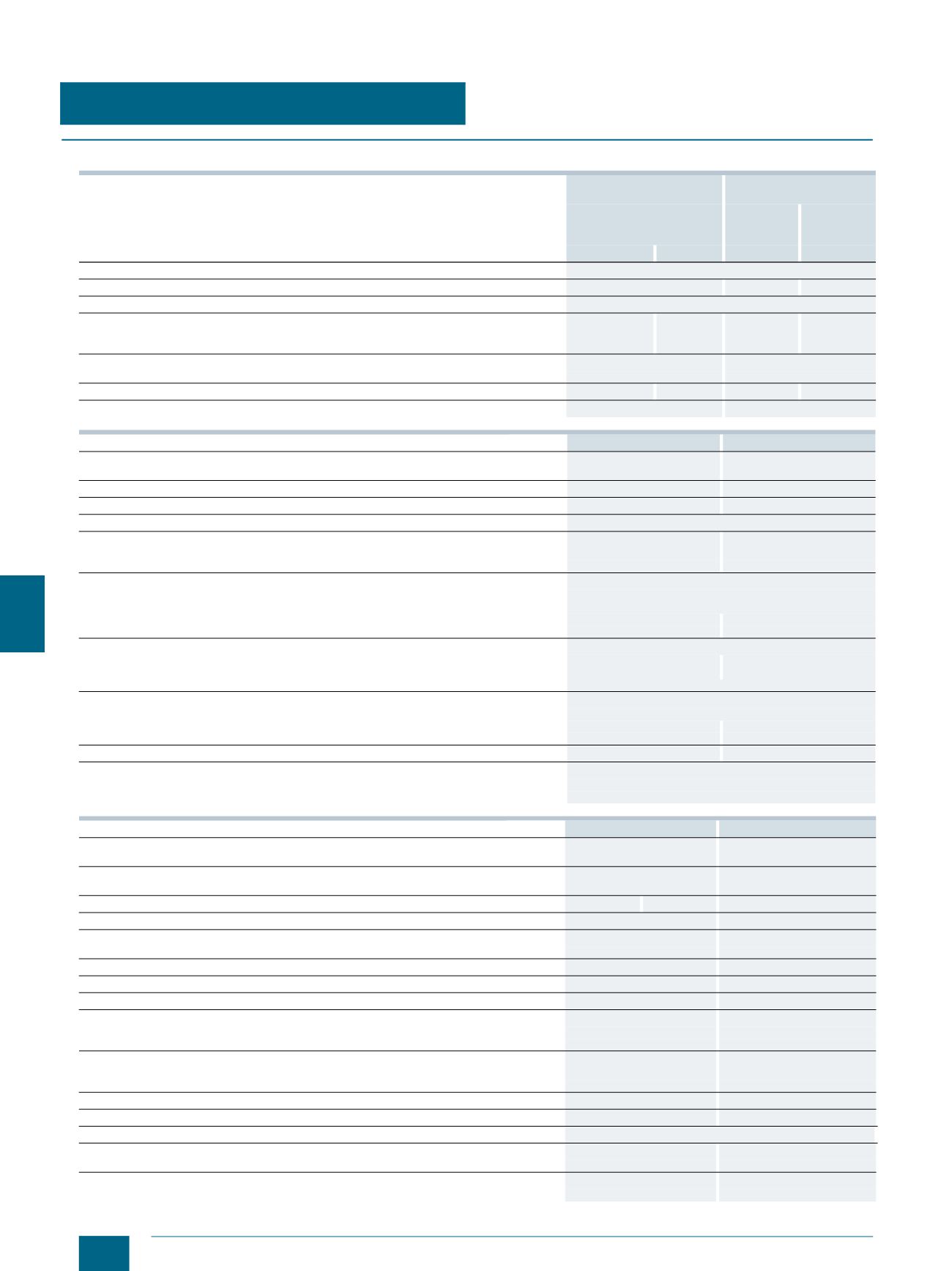
Technical specifications
1)
In the case of permanent load over 35 A, we recommend the use of 5SH5526 lateral modules. Please observe EN 60439-1, Table 1.
NEOZED SR60
bus-mounting bases
DIAZED SR60
bus-mounting bases
5SG6202
5SG6206
5SG6207
5SF6014
5SF6015
5SF6020
5SF6214
5SF6215
5SF6220
D01
D02
DII
DIII
Standards
IEC 60269-3, DIN VDE 0636-3
Rated voltage
V AC/DC 400/250
500
690/600
Rated frequency
Hz
50
Rated current
A
16 (with
NEOZED retain-
ing springs)
63
25
63
Rated conditional short-circuit current
kA AC 50
50
kA DC 8
8
For fuse links with power losses per phase
W 2.5
5.5
4
7
Busbar center-to-center spacing
mm 60
60
3NW7431
3NW7431-0HG
Standards
IEC 60269-2,
UL 512, CSA C22.2
UL 512, CSA C22.2
Approvals
U
, CSA
UL, CSA
Size
10 × 38
Class CC
Rated frequency
Hz
50/60
Max. rated voltage
U
e
• IEC/EN
V AC 690
--
• UL/CSA
V AC 600
600
Max. rated operational current
I
e
(When several devices are used next to each other, it is essential to comply with the
rated load factor according to EN 60439-1 (VDE 0660-500), Table 1)
• IEC/EN
A
32
--
• UL/CSA
A
30
30
Utilization categories
• IEC/EN
AC-22B (500 V)
AC-21B (690 V, 30 A)
• UL/CSA
Can only be used as fuse holder
Rated conditional short-circuit current
(type-tested with fuse links, operational class gL/gG)
• IEC/EN
kA
100 (400 V, 500 V, 690 V)
--
• UL/CSA
kA
50 (600 V)
200
For fuse links with power losses per phase
W 3
--
Screwless wire connections
• IEC/EN
mm
2
Cu 1.5 … 6 (f)
• UL/CSA
AWG 16 … 10 (str)
5SG7230
3NW7430
Standards
IEC 60269-3,
IEC 60269-2
IEC 60269-3,
IEC 60269-2
Approvals
EN 60947-3 (VDE 0660-107),
IEC 60947-3
EN 60947-3 (VDE 0660-107),
IEC 60947-3
Size
D01
D02
10 mm × 38 mm
Rated frequency
Hz
50/60
50/60
Rated voltage
U
e
V AC 400
690
V DC 110
--
Rated insulation voltage
U
i
V
800
800
Rated impulse withstand voltage
U
imp
kV
6
6
Rated operational current
I
e
A
63
1)
Up to 32
Utilization categories
AC-23 A (400 V)
AC-20
(type-tested with 3-pole, switchable version)
DC-21 B (48 V) – 1 Pole
DC-20
DC-21 B (110 V) – 2 Pole
Box terminals for wire connection
mm
2
Cu 1.5 … 6 (re)
Cu 1.5 … 6 (re)
mm
2
Cu 1.5 … 16 (f)
Cu 1.5 … 16 (f)
mm
2
Cu 1,.5 … 16 (f+AE)
Cu 1.5 … 16 (f+AE)
Signaling switches for the display of switching positions
1 CO
1 CO
Cable terminals
Bottom
Bottom
Busbar thickness
mm Through combination foot for 5, 10 mm
Rated conditional short-circuit current
kA AC 50
50
(type-tested with fuse links, operational class gL/gG)
kA DC 8
--
Permissible power loss of fuse links per phase
W 5.5
3
For stand-alone operation without lateral modules or for group operation with lateral modules
© Siemens AG 2014