


 31 / 38

Busbar Systems
Distribution board components
10/31
Siemens LV 10 · 2014
10
■
Overview
Material properties
Busbar supports and busbar-mounting fuse bases (
see "Built-in
components" from page 10/33
) are manufactured from glass-
fiber reinforced, thermoplastic polyester (color RAL 7035, light
gray). The material ensures excellent mechanical, chemical and
electrical properties. Furthermore, the material has an extremely
low flammability and meets the requirements of UL 94 V0. This
satisfies the load requirements of the busbar supports at rated
operational voltage 500 V and rated currents at 200 A to 630 A,
as well as the rated short-circuit strength 50 kA.
Ambient temperatures
When dimensioning the busbars based on rated currents, the
ambient temperature and the Cu busbar temperature must also
be taken into account.
The location of the busbar system and its ability to dissipate heat
through convection also play a key role in this calculation. Be-
cause conditions can vary for each distribution board, the values
in the following table serve as a guideline only. However, they
must be applied to the entire busbar length.
Continuous currents depending on the Cu power rail dimensions and Cu busbar temperatures
at 35 °C ambient temperature
Dynamic rated short-circuit strength
The electrodynamic load of the busbars depends on the level of
short-circuit current, the length of the busbar section through
which the current flows, the support spacing of the busbar sup-
ports and, of course, on the distance between the busbars them-
selves. This is because, for example, if an LV HRC fuse is con-
nected upstream to the busbars in the protective device, the let-
through current
i
D
is the maximum current to flow through this
protective device. The value
i
D
depends on the maximum sys-
tem short-circuit current and the current-limiting action of the
protective device used. The permissible let-through values of
the protective devices are specified by the manufacturers in the
form of a current limitation diagram as a function of the so-called
prospective short-circuit current (r.m.s. value of the possible
rated short-circuit current for the system).
The current-limiting characteristics for the fuse links can be
found in the Technical Information,
see note on Technical
Information at the beginning of the chapter.
For busbar supports with busbars of 12 mm x 5 mm to 20 mm x
5 mm, the distance between the holders of the support spacing
should be adapted to suit the bars in the distribution board and,
if possible, should not exceed 250 mm. When using busbars of
25 mm x 5 mm, 30 mm x 5 mm, 12 mm x 10 mm to 30 mm x
10 mm the distance can also be up to 500 mm. In the case of
larger distances, subcarriers must be fitted, as increased sup-
port spacing reduces the dynamic stability.
It is essential to ensure that the permissible current carrying ca-
pacity of the individual busbars is not exceeded. A center infeed
is required in the limit range. However, the infeed can also be
carried out at both ends of the busbar.
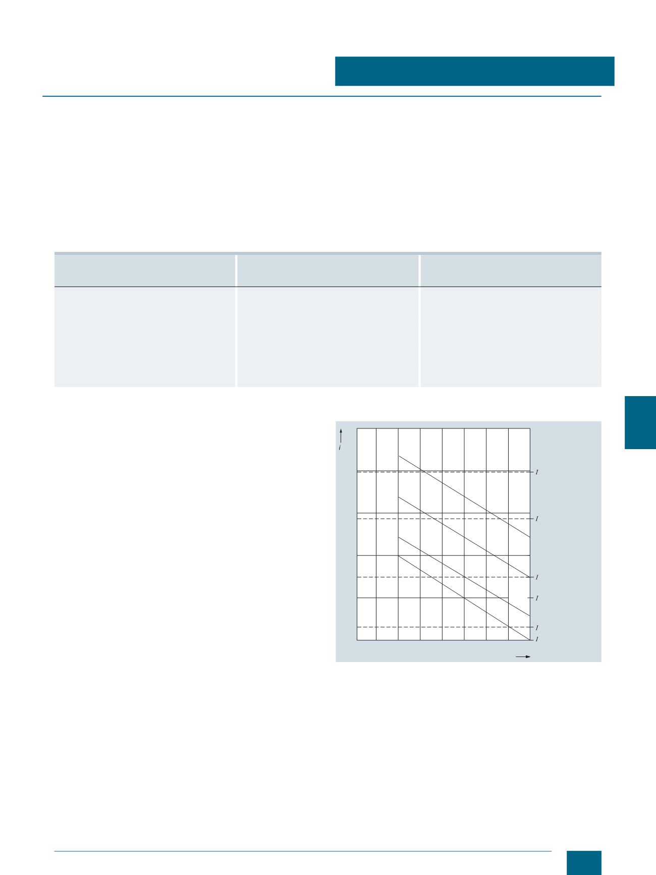
Diagram of the dynamic short-circuit strength of the busbars
i
D
:
Let-through values (kA) of the LV HRC fuse links, operational class
gL/gG with rated current 200 A to 630 A for a prospective short-circuit
current
I
p
= 120 kA.
Cu busbar dimensions
H × D
Continuous current for open busbar run -
ambient temperature 35 °C
Continuous current of fuse link
Operational class gL/gG
mm × mm
A
A
12 × 5
200
200
12 × 10
360
315
15 × 5
250
250
15 × 10
447
400
20 × 5
320
315
20 × 10
520
500
25 × 5
400
400
25 × 10
580
500
30 × 5
447
400
30 × 10
630
630
As far as other types of upstream protective devices are concerned, please observe the permissible continuous current of the busbar.
30
40
50
60
70
80
150 200 250 300 350 400 450 500 550
D
[kA]
n
200 A
n
250 A
n
315 A
n
400 A
n
500 A
n
630A
20x5
12x5
20x10
12x10
30x5
30x10
Distance between busbar support in mm
Busbar dimension
mm
Let-through current
of the fuse links
Operating class
gL/gG
I201_07483a
© Siemens AG 2014