


 32 / 38

Busbar Systems
Distribution board components
10/32
Siemens LV 10 · 2014
10
Planning dimensions
Number of built-in components that can be mounted
■
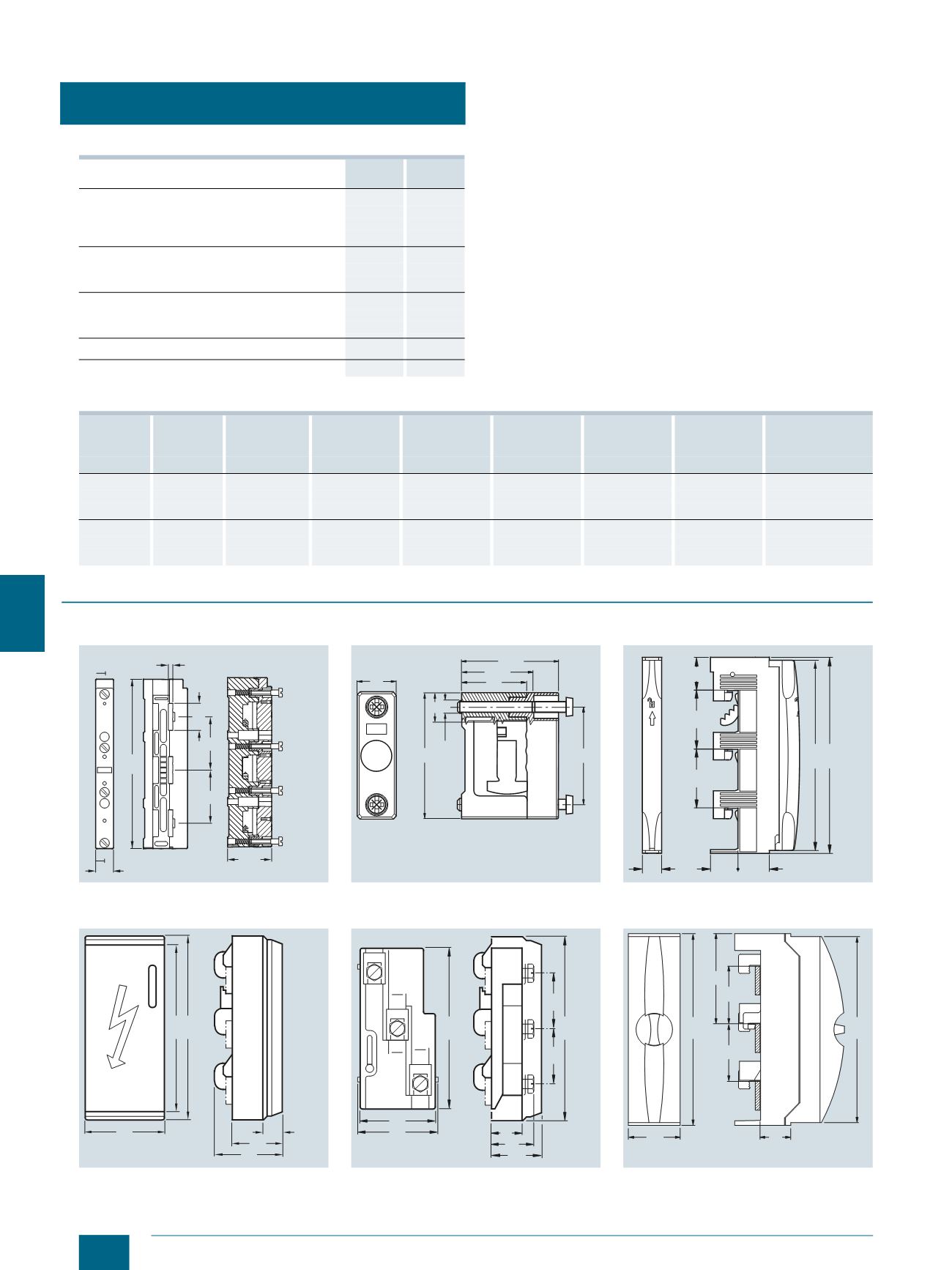
Dimensional drawings
Width
mm MW
NEOZED bus-mounting bases D02
Covers
27
1.5
Covers, extra wide
36
2.0
Covers, double width
54
3.0
DIAZED bus-mounting bases DII
Covers
42
2.3
Covers, double width
84
4.7
DIAZED bus-mounting bases DIII
Covers
57
3.2
Covers, double width
114
6.3
NEOZED bus-mounting switch disconnectors
27
1.5
LV HRC fuse switch disconnectors size 00
108
6
Height
Width
Cutout width D02/63 A
5SH5241
D02/63 A
5SH5242
D02/63 A
5SH5243
DII/25 A
5SH2042
DIII/63 A
5SH2242
5SG7230 bus-
mounting switch
disconnectors D02
mm
mm
mm
(27 mm width) (36 mm width) (54 mm width) (42 mm width) (57 mm width) (26.8 mm width)
300
250
216
8
6
4
5
3
8
500
466
17
12
8
11
8
17
750
716
26
19
13
17
12
26
450
250
216
8
6
4
5
3
8
500
466
17
12
8
11
8
17
750
715
26
19
13
17
12
26
8GK9 busbar support
N/PE busbar support
Connection modules
8GK9711-0KK03
5SH3540
5SH5538
Connection modules
Connection modules
Connection modules
8US1921-1AA00
shown closed
8US1921-1AA00
shown open
8US1921-1BA00
A
A
5
49,5
30,5
191
20
60
60
SECTION: A-A
NSE0_01568a
6,5 15
65
4 Nm
49,5
50
33
36,5
I201_14000a
20
20
28
60
34
60
32
200
194
I201_13999a
I201_07150
84
20
55
70
200
189
60
60
200
31
46
80
84
175
I201_06439
55
200
194
54
60
94
60
32
NSE0_01598
© Siemens AG 2014