


 100 / 253

13/4
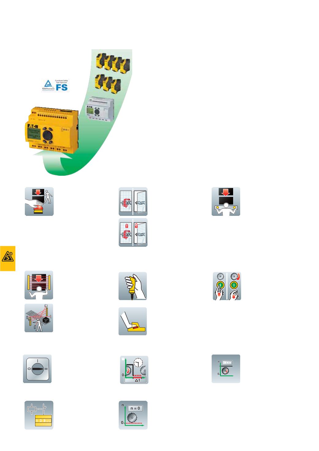
Safety relays
2010
CA08103002Z-EN
www.eaton.comSafety
Safety
Description
The easySafety control relay for safety-related applications monitors all commonly
used safety devices and also takes over the required control tasks for the machine.
Packed with a host of conventional safety relays in the form of safety function blocks,
easySafety not only features integrated safety functions but also standard functions
in a single device – all in one.
In addition to the safety circuit diagram containing the safety configuration, the safety
control relay also contains a standard circuit diagram. This circuit diagram can be
used for standard tasks, such as the processing of diagnostics signals or general
control tasks of a machine.
Thanks to the large number of safety function blocks, this provides the user with a
number of application options with only one device. The user can now also respond
directly to future and changing application requirements. This saves financial
resources and offers future investment security. Last but not least, it reduces the
stock-keeping required for special safety relays.
easySafety meets the requirements of category 4 to EN 954‐1, PL e to EN ISO 13849‐1,
SILCL 3 to EN IEC 62061 and SIL 3 to EN IEC 61508. With easySafety, it is therefore
possible to implement applications meeting the most stringent safety requirements.
In addition to many standard function blocks from the easy800, easySafety offers the following safety function blocks:
Emergency stop circuits
Allows the safe stopping of a
hazardous movement,
immediate stop for Stop
category 0 and controlled
stop for Stop category 1
according to IEC 60204-1; for
use in single or dual channel
safety monitoring of emer-
gency stop circuits.
Guard door monitoring with
andwithout interlock/guard
locking
Used with moving guards
such as doors, barriers or
flaps. Positions are reliably
detected, monitored and
enabled to safety-related
requirements – optional
interlock device with guard
locking when increased
personal and process
protection are required; this
securely keeps the guard
closed until machine
standstill.
Safe operationwith two-hand
control
Type III to EN 574. Used for
hazardous machine move-
ment such as presses,
punching, shearing. It allows
the movement of hazardous
operation only when both
hands of the operator are out-
side the hazardous area and
the two pushbuttons are
operated within 0.5 seconds of
each other.
Electro-sensitive protective
devices (ESPE)
Protection of the hazardous
location or area in the vicinity
of machines by means of
contactless guards such as
light grids/light barriers/light
curtains.
Optionally with muting
function,
which temporarily bypasses
the protective function of a
safety device, such as a light
curtain. Typical applications
include feedingmaterials into
a machine without having to
interrupt the machine's
operation.
Enabling switch
The manual or foot operated
enable switch allows the
temporary enabling of a
guard, such as a safety door,
by continuous actuation.
This may be necessary for
setting or servicing a
machine.
Start device
For the safe starting of an
application by means of an
external start pushbutton or
start condition from the safety
circuit diagram.
Operating mode selector
switches
Used for the safe selection
and acceptance of a prese-
lected operating mode on an
external control circuit
device.
Safety timing relay
Used for changing the
switch duration and the on
or off switch points of an
enable contact in the safety
circuit. Safety-related timing
relay with on and/or off
delayed or single pulse
function.
Overspeed monitoring
For the safety-related
overspeed monitoring of a
motor or a shaft. If the
maximum speed is exceeded,
the drive is disabled.
Feedback loop monitoring
(
EDM)
Used for the safety-related
monitoring of externally
connected actuators, e.g.
contactors, relays or valves.
Zero monitoring
Used when the entry or
access to the hazardous
area is not permitted until
the hazardous driving force
has come to a standstill.
u
n < x
. .
1 2 3