


 180 / 439

6/32
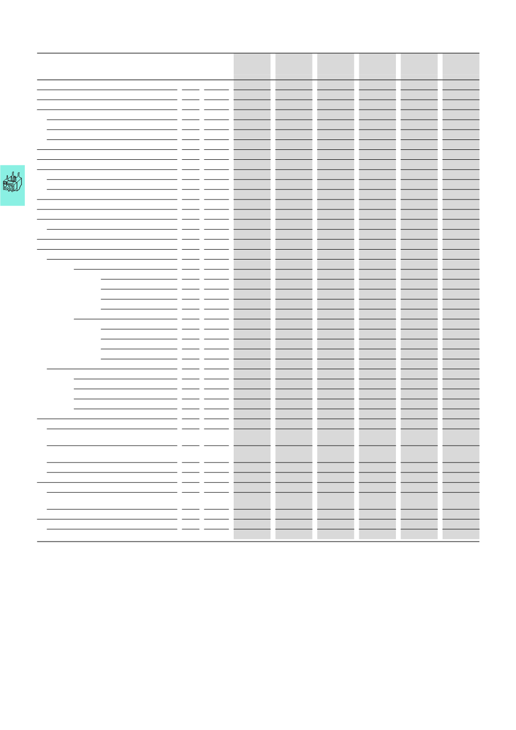
Overload relays
Overload relays, CT-operated overload relays
2010
CA08103002Z-EN
www.eaton.comOverload relays,CT-operatedoverload relays
ZE
ZB12, ZB32 ZB65
ZB150(KK)
Z5-.../FF225
Z5-.../FF250
ZW7
Auxiliary and control circuits
Rated impulse withstand voltage
U
imp
V
6000
6000
6000
6000
6000
6000
Overvoltage category/Pollution degree
III/3
III/3
III/3
III/3
III/3
III/3
Terminal capacity
Solid
mm
2
2
x (0.75 - 2.5) 2 x (0.75 - 4)
2
x (0.75 - 4)
2
x (0.75 - 4)
2
x (0.75 - 4)
2
x (0.75 - 4)
Flexible with ferrule
mm
2
2
x (0.5 - 1.5)
2
x (0.75 - 2.5) 2 x (0.75 - 2.5) 2 x (0.75 - 2.5) 2 x (0.75 - 2.5) 2 x (0.75 - 2.5)
Solid or stranded
AWG 2 x (18 - 12)
2
x (18 - 12)
2
x (18 - 12)
2
x (18 - 12)
2
x (18 - 12)
2
x (18 - 12)
Terminal screw
M3.5
M3.5
M3.5
M3.5
M3.5
M3.5
Tightening torque
Nm 0.8 - 1.2
0.8 - 1.2
0.8 - 1.2
0.8 - 1.2
0.8 - 1.2
0.8 - 1.2
Tools
Pozidriv screwdriver
Size
2
2
2
2
2
2
Flat-blade screwdriver
mm 0.8 x 5.5
1
x 6
1
x 6
1
x 6
1
x 6
1
x 6
Auxiliary circuit rated insulation voltage
U
i
V AC 690
500
500
500
500
500
Rated operating voltage
U
e
V AC 500
500
500
500
500
500
Safe isolation according to EN 61140
Between the auxiliary contacts
V AC 300
240
240
240
240
240
Conventional thermal current
I
th
A
6
6
6
6
6
6
Rated operational current
AC-15
N/O
120
V
I
e
A
1.5
1.5
1.5
1.5
1.5
1.5
240
V
I
e
A
1.5
1.5
1.5
1.5
1.5
1.5
415
V
I
e
A
0.5
0.5
0.5
0.5
0.5
0.5
500
V
I
e
A
0.3
0.5
0.5
0.5
0.5
0.5
NC
120
V
I
e
A
1.5
1.5
1.5
1.5
1.5
1.5
240
V
I
e
A
1.5
1.5
1.5
1.5
1.5
1.5
415
V
I
e
A
0.7
0.9
0.9
0.9
0.9
0.9
500
V
I
e
A
0.5
0.8
0.8
0.8
0.8
0.8
DC-13 L/R ≦ 15 ms
1)
24
V
I
e
A
0.9
0.9
0.9
0.9
0.9
0.9
60
V
I
e
A
0.75
0.75
3)
0.75
3)
0.75
3)
0.75
3)
0.75
3)
110
V
I
e
A
0.4
0.4
0.4
0.4
0.4
0.4
220
V
I
e
A
0.2
0.2
0.2
0.2
0.2
0.2
General Use
AC operated
V
240
600
–
–
–
–
–
AC operated
A
1.5
0.6
–
–
–
–
–
DC operated
V
–
–
–
–
–
–
DC operated
A
–
–
–
–
–
–
Pilot Duty
AC operated
D300
B300
4)
B600
5)
B300
4)
B600
5)
B300
4)
B600
5)
B300
4)
B600
5)
B300
4)
B600
5)
DC operated
R300
R300
R300
R300
R300
R300
Short-circuit rating without welding
Max. fuse
2)
A gG/gL 4
6
6
6
6
6
Notes
1)
Making and breaking conditions to DC-13, time constant as stated
2)
See transparent overlay "Fuses" for time/current characteristics (please enquire)
3)
Rated operational current DC-13, 60 V: N/O auxiliary contact 0.6 A
4)
With opposite polarity
5)
With same polarity
ZE, ZB, Z5, ZW7