


 26 / 51

2010
CA08103002Z-EN
www.eaton.comSwitchgear for North America 22/13
Classified Components according to
CSA. They have non-adjustable
magnetic short-circuit releases for
short-circuit protection and fixed-
current overload relays for overload
protection. They are approved as
current limiters and marked accord-
ingly on their rating plates. This means
that their rated current can be fully
utilized. They are rated in amperes,
their short-circuit switching capacity
is given in kA and – if they are
equipped with auxiliary contacts –
contain duty type information (pilot
duties). Eaton also provides an
approved DC switching capacity for
single-pole 48 V and two-pole 96 V in
addition to the switches’ AC switching
capacity
1)
.
These miniature circuit breakers can
be used as branch circuit protective
devices (BCPD) in feeder circuits and
branch circuits. Up to a rated current
of 32 A, FAZ…-NA and FAZ…-RT must
be used only in star networks with
solid grounding and a slash voltage of
up to 480Y/277V. FAZ…-NA and
FAZ…-RT for higher current values
can be used up to 240 V AC, irrespec-
tive of network configuration and
grounding. Part number suffix “-RT”
stands for Ring Terminal. On these
versions the terminal screws can be
fully turned out to allow the connection
of ring cable lugs.
These circuit breakers are available
with one, two or three poles and with
IEC/EN tripping characteristics B, C
and D. The characteristic is selected
according to the protected load type.
Available accessories are auxiliary
contacts, shunt releases and three-
phase commoning links with large
clearances and creepage distances
are available.
Accessories, such as auxiliary
contacts and shunt releases
In North America, approvals were, for
a long time, available only for
complete, unalterable devices. For the
practice common in Europe of
allowing customers to retrofit devices
with auxiliary contacts, undervoltage
releases, shunt releases and other
accessories, the corresponding UL
and CSA approvals can now be issued.
This applies even for changes in the
main current area, for example
different main current terminal types.
The permissible versions must, of
course, have been described, tested
and approved. Permissible alternative
connection blocks must be indicated
on the device’s rating plate. Observe
the installation instructions and do not
omit any parts only because their
purpose is not clear. These parts
ensure the required clearances and
creepage distances, prevent short-
circuits between phases due to faulty
insulation and improve protected
against accidental contact.
The tried-and-tested modular design
method allows the field of application
of contactors, circuit breakers, motor-
protective circuit breakers, position
switches and control circuit devices to
be cost-effectively extended with
add-on functions. It also helps reduce
manufacturers and users reduce their
parts stock and provide optimized
solutions more quickly.
The standardized continuous currents
and switching duties for AC and DC for
auxiliary switches are assigned
according to the standards to the
characteristic values and switching
duty types indicated in the devices’
technical specifications and on their
ratings plates. These pilot duties are
given in the table for auxiliary contacts
in AC and DC circuits on page 5/xx.
Auxiliary contacts are approved
mainly for heavy pilot duty, and on
some devices for standard pilot duty.
For detailed information, see the
technical data for the device groups.
The ratings plate on some auxiliary
switches contains information such as
“600
V, same polarity”. This means that
adjacent auxiliary contacts of the
same auxiliary switch or switch block
must be connected only to the same
control voltage source.
Soft starters and frequency
inverters
Soft starters DS4, DS6, DS7
Like IEC/EN 60947, North American
standards regard soft starters largely
like contactors. These devices are
developed, tested and approved to
UL 508, CSA-C22.2 No. 14-05 and
CSA-C22.2 No. 0-M91. Circuit-breakers
or fuses provide short-circuit protec-
tion. The North American standards do
not currently include protection
through UL 508 Type E starters or the
treatment of these devices as contac-
tors, i.e. as UL 508 Type F starters.
Motor protection must be provided by
an overload relay. For dimensioning
the motor outgoer with soft starter, use
the selection tables in this catalog.
Eaton’s soft starters (DS4, DS6, DS7)
are UL-listed and CSA-certified (DS7
as of Summer 2010) for an operational
voltage of up to 480 V 50/60 Hz (full
voltage). They are used in branch
circuits. In practice, the soft starters
are bypassed with a built-in bypass
after the motor has started up. This
reduces heat losses and thyristor load.
Any short-circuit currents in the motor
outgoer do not flow through the
thyristors in the event of a fault. This
increases the soft starters’ reliability.
On some models the soft starters
switch two phases and the third phase
is fed through. One of of the competi-
tive advantage of Eaton’s soft starters
is that they have terminal types that
are adapted to the switchgear. At
currents up to 41 A the same terminal
types are used as for circuit breakers,
whose accessories can therefore also
be used.
Frequency inverters M-Max
and H-Max
Frequency inverters are developed,
tested and approved according to
North American standards UL 508C
and CSA-C22.2 No.14-05. Short-circuit
protection is provided by circuit
breakers or fuses. It is currently not yet
clear whether UL 508 Type E or Type F
starters can be used as protective
devices. Frequency inverters can be
used only in combination with the
tested, manufacturer-assigned
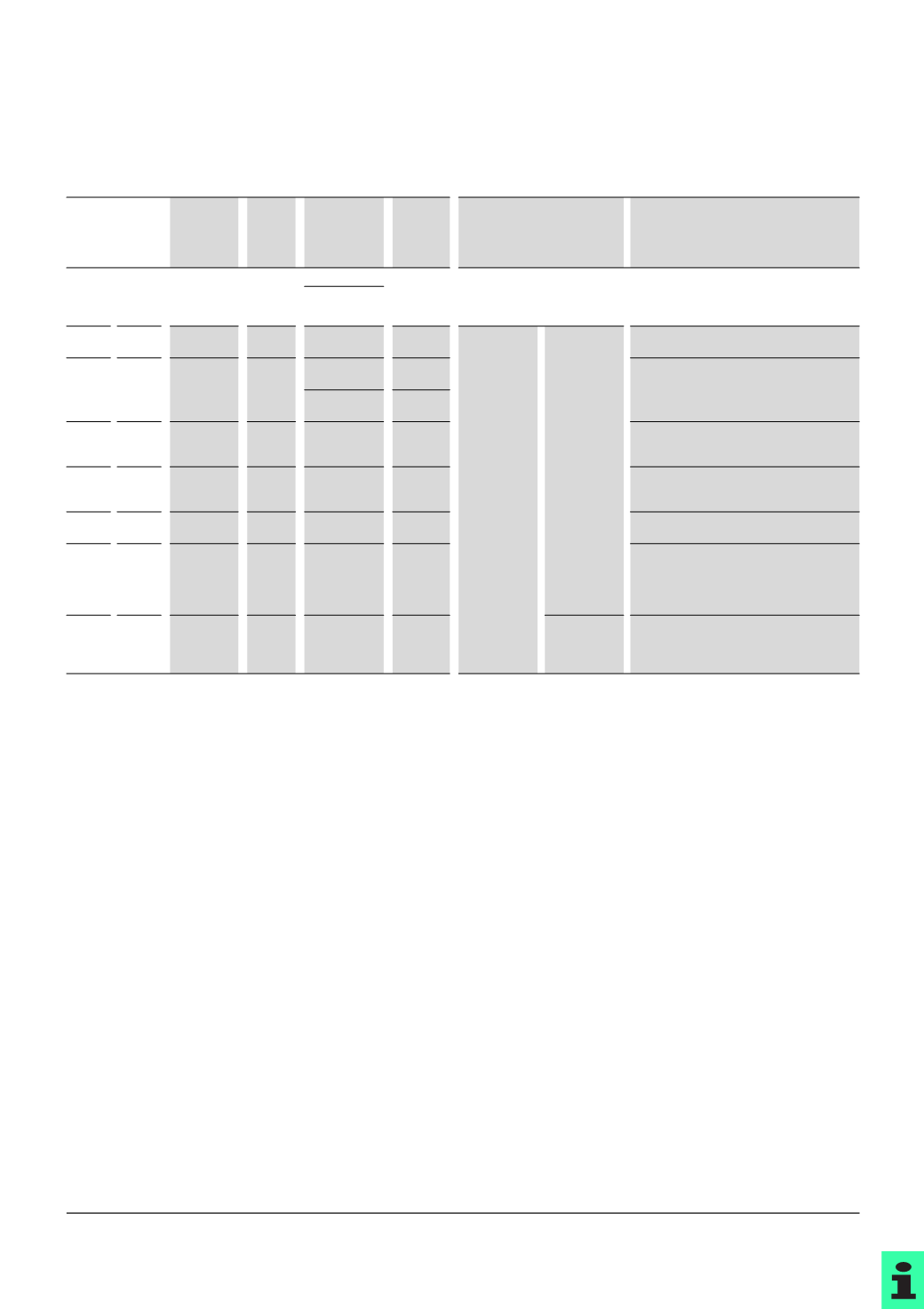
Part no.
or design in:
Standards
UL, CSA
Fuse
charac-
teristics
SCCR
Typical
values
in A
Fields of application
Notes
USA Canada
Class
H
,
"
Code"
Class
H
,
No. 59
"
Code"
UL 248-6/7,
C22.2 248-6/7
Fast
10
kA, 250 VAC
0…600
Primarily domestic
Types H, K and No. 59 “Code” fit the same bases
and are therefore interchangeable. There is
therefore a risk that they may be incorrectly
used! See also note on K.
10
kA, 600 VAC
Class
CC
Class
CC
UL 248-4,
C22.2 248-4
Fast
Time-lag
200
kA,
600
VAC
0.5…30
Fast
:
Protection
from resistive
and inductive
loads.
Circuits for
heating,
lighting, feed-
ers and
branches for
mixed loads.
Time-lag:
Protection
from inductive
and highly
inductive
loads.
Circuits for
motors,
transformers,
lighting etc.
Extremely compact design.
Current limiter
to UL/CSA.
Class
G
Class
G
UL 248-5,
C22.2 248-5
Fast
Time-lag
100
kA,
480
VAC
21…60
Compact design.
Current limiter
to UL/CSA.
All other fuse types do not fit into bases.
100
kA,
600
VAC
0.5…20
Class
J
Class
J
HRCI-J
UL 248-8,
C22.2 248-8
Fast
Time-lag
200
kA,
600
VAC
1…600
Compact design.
Current limiter
to UL/CSA.
All other fuse types do not fit into bases.
Class
K
K1, K5
Class
K
K1, K5
UL 248-9,
C22.2 248-9
Fast
Time-lag
50
kA/100 kA/
200
kA,
600
VAC
0…600
Not current limiter
to UL/CSA.
In the USA, the K types are therefore being
increasingly replaced by the RK part numbers.
Class
L
Class
L
UL 248-10,
C22.2 248-10
Fast
Time-lag
200
kA,
600
VAC
601…6000
Current limiter
to UL/CSA.
All other fuse types do not fit into bases.
Class
R
RK1,
RK5
Class
R
HRCI-R
RK1,
RK5
UL 248-12,
C22.2 248-12
Fast
Time-lag
50
kA/100 kA/
200
kA,
600
VAC
0…600
Current limiter
to UL/CSA.
Types RK1, RK5 and HRCI-R fit the same bases.
All other fuse types do not fit into these bases.
RK1 fuses have lower let-through values than
RK5.
Class
T
Class
T
UL 248-15,
C22.2 248-15
Fast
200
kA,
300
VAC
200
kA,
600
VAC
0…1200
_
Extremely compact design.
Current limiter
to UL/CSA.
All other fuse types do not fit into bases.
Notes
1)
For additional approved versions for single-pole 125 V DC and two-pole
250
V DC please enquire