


 534 / 578

534
Emergency Lighting
Regulations - Glare
When designing an emergency
lighting scheme, levels of glare must
be carefully considered
Cd/1000lm
150°
120°
90° 1800 1200 600
90°
60°
60°
30°
0°
30°
120°
150°
Voyager LED Route
Lamp:
1xHigh power LED
Flux:
115lm
Power:
2.2W
Cd/1000lm
150°
120°
90° 300 200 100
90°
60°
60°
30°
0°
30°
120°
150°
Voyager LED Area
Lamp:
1xHigh power LED
Flux:
115lm
Power:
2.2W
Cd/1000lm
150°
120°
90° 1200 800 400
90°
60°
60°
30°
0°
30°
120°
150°
Voyager LED Spot
Lamp:
1xHigh power LED
Flux:
115lm
Power:
2.2W
Emergency fittings should be positioned to be free from disability glare.
Disability glare is where the brightness of the luminaire dazzles people,
preventing obstructions or signs from being properly seen.
The table below shows the permitted glare limits, as set out in the current
standard.
Horizontal Routes
The glare calculation takes into account the number of luminaires that can be
seen and the contribution of glare from each of these fittings. For horizontal
routes, any glare above 60° is considered to contribute to the disability glare
values.
Change of Level
Wherever there are changes in level, glare levels should not be exceeded at
all angles.
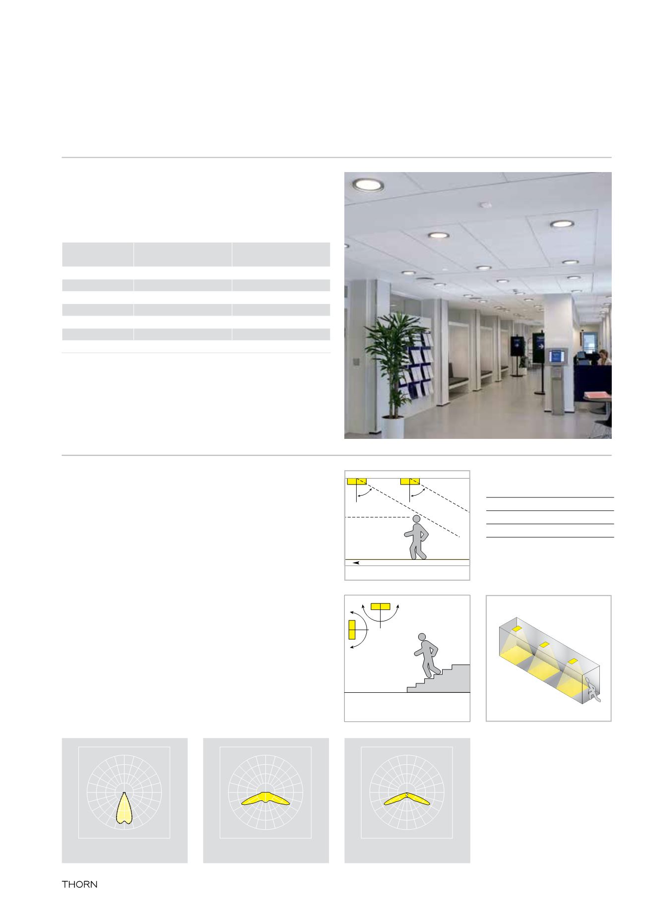
In the example shown in diagram 1, the Voyager Elite luminaires are mounted
transversely (with their longest point facing across the corridor)
at a height of 2.4 metres.
There are three emergency luminaires in the field of view. Therefore, the level of
disability glare is calculated as follows:
3 x 64.2 = 192.6cd
This value is significantly below the
500cd
for luminaires mounted at 2.4 metres.
Mounting Height h EscapeRoute&OpenArea
Max.LuminousIntensityImax
HighRisk
Max.LuminousIntensityImax
m
cd
cd
h<2.5
500
100
2.5≤h<3.0
900
1800
3.0≤h<3.5
1600
3200
3.5≤h<4.0
2500
5000
4.0≤h<4.5
3500
7000
4.5<h
5000
10000
60˚
Glare zone
Line of sight
Contributory
Direction of escape
60˚
180˚
180˚
60˚
Glare zone
Line of sight
Contributory
Direction of escape
60˚
180˚
180˚
Disability glare data
Maximum intensity (cd)
Transverse Axial
Level route 60-90˚
64.2
8.0
Non-level route 0-90˚ 64.2
27.0
Glare
Diagram 1
www.thornlighting.co.uk