


 34 / 221

34
DR series lugs are manu-
factured from electrolytic
Copper tube and designed
to obtain high electrical
conductivity combined with
the mechanical strength
required to resist vibration
and pull out.
Cembre lugs are annealed
and Tin plated for improved
surface protection.
The annealing process
optimises the structural
features of the material al-
lowing easier crimping and
greater resistance to me-
chanical stresses.
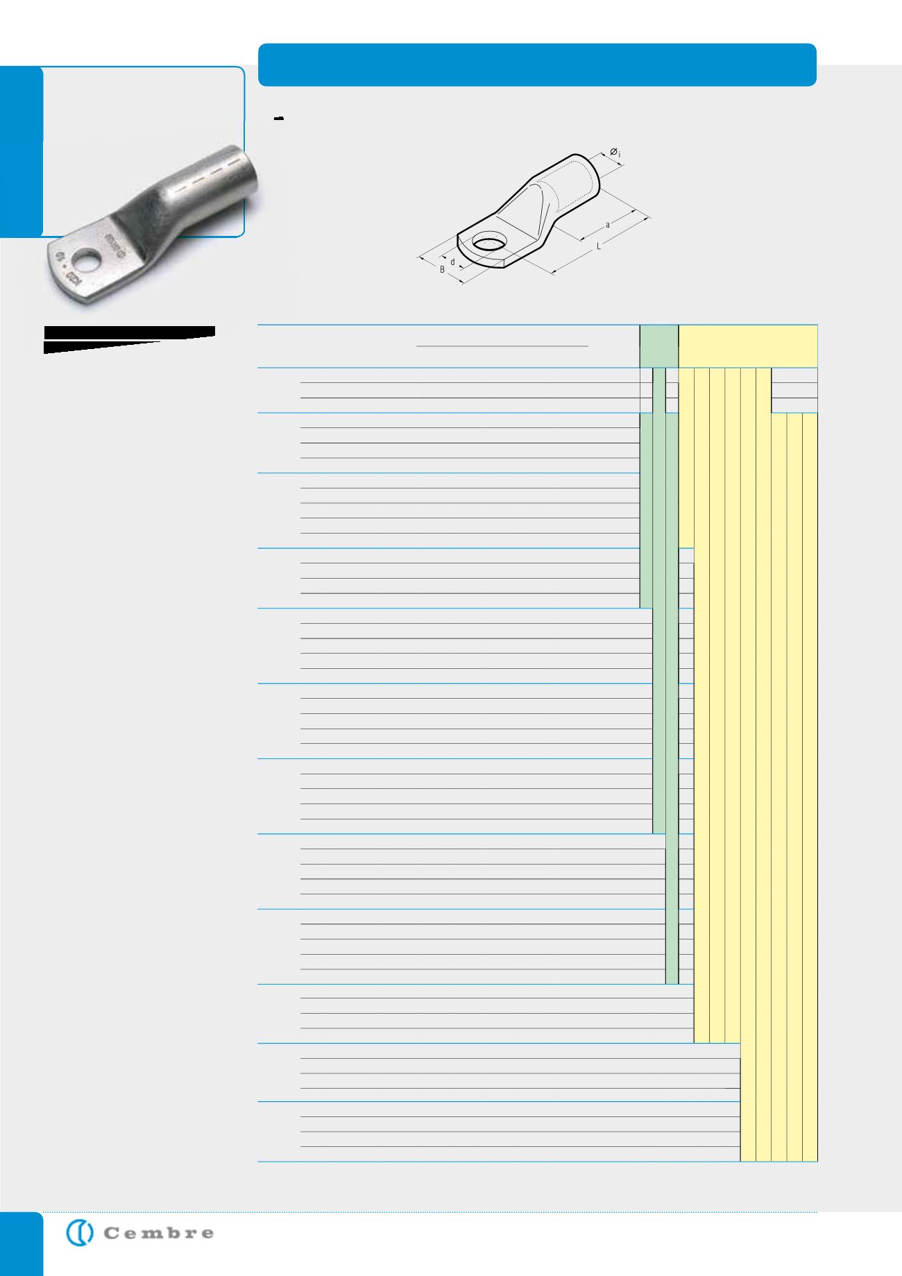
Dimensions are according
to DIN 46235.
The barrel entrance of the
lug is chamfered to allow
easy conductor insertion,
while its length facilitates
precise positioning in the
crimping die.
Each lug is marked with:
- Cembre logo and part
code.
- conductor type and csa
(mm
2
).
- Stud Ø (mm).
- crimping die code
Details of the appropriate
crimping tools and dies are
shown on page 189.
Consult us for special
requirements
COPPER TUBE CRIMPING LUGS ACCORDING TO DIN 46235
for Copper conductors
DR
Conductor
Size
sqmm
Ø
Stud
mm
Ref.
Code
D i m e n s i o n s m m
Quantity
Box/Bag
Mechanical
Tools
Hydraulic
Tools
Ø
i
d
L
B
a
6
5
DR6-5
5 3,8 5,3 24,0 8,5 10,0
800/100
TND 6-70
B 15MDE
B 35-45MDE
B 35-50M0E
HT 45-E
HT 51 RH 50 B 500E
HT 81-U RHU 81
6
DR6-6
5 3,8 6,4 24,0 9,0 10,0
800/100
8
DR6-8*
5 3,8 8,4 26,0 13,0 10,0
800/100
10
5
DR10-5
6 4,5 5,3 27,5 10,0 10,0
800/100
HN-D25
TND 10-120
HT 120 and tools and heads with 130 kN crimping force
ECW-H3D
RHU 520
6
DR10-6
6 4,5 6,4 27,0 10,0 10,0
800/100
8
DR10-8*
6 4,5 8,4 28,0 13,0 10,0
800/100
10
DR10-10*
6 4,5 10,5 28,5 15,0 10,0
800/100
16
5
DR16-5*
8 5,5 5,3 36,0 13,0 20,0
400/100
6
DR16-6
8 5,5 6,4 36,0 13,0 20,0
400/100
8
DR16-8
8 5,5 8,4 37,0 13,0 20,0
400/100
10
DR16-10
8 5,5 10,5 40,0 17,0 20,0
400/100
12
DR16-12*
8 5,5 13,0 41,0 19,0 20,0
400/100
25
6
DR25-6
10 7,0 6,4 39,0 14,6 20,0
400/100
8
DR25-8
10 7,0 8,4 39,5 16,0 20,0
400/100
10
DR25-10
10 7,0 10,5 40,0 17,0 20,0
200/100
12
DR25-12
10 7,0 13,0 40,5 19,0 20,0
200/100
35
6
DR35-6*
12 8,2 6,4 42,5 17,5 20,0
200/100
8
DR35-8
12 8,2 8,4 42,0 17,0 20,0
200/100
10
DR35-10
12 8,2 10,5 43,0 19,0 20,0
200/100
12
DR35-12
12 8,2 13,0 43,0 21,0 20,0
200/100
16
DR35-16*
12 8,2 17,0 44,0 28,0 20,0
200/100
50
6
DR50-6*
14 10,0 6,4 52,0 20,0 28,0
100/25
8
DR50-8
14 10,0 8,4 52,0 20,0 28,0
100/25
10
DR50-10
14 10,0 10,5 53,0 22,0 28,0
100/25
12
DR50-12
14 10,0 13,0 53,0 24,0 28,0
100/25
16
DR50-16
14 10,0 17,0 57,0 28,0 28,0
100/25
70
8
DR70-8
16 11,5 8,4 56,0 24,0 28,0
50/25
10
DR70-10
16 11,5 10,5 56,0 24,0 28,0
50/25
12
DR70-12
16 11,5 13,0 56,0 24,0 28,0
50/25
16
DR70-16
16 11,5 17,0 60,0 30,0 28,0
50/25
20
DR70-20*
16 11,5 21,0 84,5 30,0 28,0
50/25
95
8
DR95-8*
18 13,5 8,4 65,0 28,0 35,0
50/25
10
DR95-10
18 13,5 10,5 66,0 28,0 35,0
50/25
12
DR95-12
18 13,5 13,0 66,0 28,0 35,0
50/25
16
DR95-16
18 13,5 17,0 65,5 32,0 35,0
50/25
20
DR95-20*
18 13,5 21,0 71,0 33,0 35,0
50/25
120
8
DR120-8*
20 15,5 8,4 70,0 31,0 35,0
50/25
10
DR120-10
20 15,5 10,5 70,0 32,0 35,0
50/25
12
DR120-12
20 15,5 13,0 70,5 32,0 35,0
50/25
16
DR120-16
20 15,5 17,0 70,0 32,0 35,0
50/25
20
DR120-20
20 15,5 21,0 72,0 36,0 35,0
50/25
150
10
DR150-10
22 17,0 10,5 79,0 34,0 35,0
50/25
12
DR150-12
22 17,0 13,0 78,5 34,0 35,0
50/25
16
DR150-16
22 17,0 17,0 78,0 34,0 35,0
50/25
20
DR150-20
22 17,0 21,0 78,0 40,0 35,0
50/25
185
10
DR185-10
25 19,0 10,5 83,0 37,0 40,0
25/25
12
DR185-12
25 19,0 13,0 82,5 37,0 40,0
25/25
16
DR185-16
25 19,0 17,0 82,0 37,0 40,0
25/25
20
DR185-20
25 19,0 21,0 83,0 40,0 40,0
25/25
240
10
DR240-10*
28 21,5 10,5 92,0 42,0 40,0
20/10
12
DR240-12
28 21,5 13,0 92,0 42,5 40,0
20/10
16
DR240-16
28 21,5 17,0 92,0 42,5 40,0
20/10
20
DR240-20
28 21,5 21,0 92,0 45,0 40,0
20/10
* Dimensions of the tube according to DIN 46235; Stud hole not included within the standard.