


 185 / 300

Furse, Wilford Road, Nottingham, NG2 1EB • Tel: +44 (0)115 964 3700 • Email:
enquiry@furse.com• Web:
www.furse.comESP 415/XXX Series
TSC-0912 - 09.10.12
Electrical specification
ESP 415/I/TNS ESP 415/III/TNS ESP 415/I/TNC ESP 415/III/TNC ESP 415/I/TT ESP 415/III/TT
Nominal voltage - Phase-Neutral
U
o
(RMS)
240 V
Maximum voltage - Phase-Neutral
U
c
(RMS/DC)
320 V/420 V
Temporary Overvoltage TOV
U
T
1
350 V
Short circuit withstand capability
25 kA/50 Hz
Frequency range
47-63 Hz
Max. back-up fuse
(see installation instructions)
250 A
Leakage current
(to earth)
< 2.5 mA
< 2.5 mA
< 2.5 mA
< 2.5 mA
-
-
Volt free contact
- current rating
- nominal voltage
(RMS)
Screw terminal
0.5 A
250 V
Transient specification
ESP 415/I/TNS ESP 415/III/TNS ESP 415/I/TNC ESP 415/III/TNC ESP 415/I/TT ESP 415/III/TT
Type 1 (BS EN/EN), Class I (IEC)
Nominal discharge current 8/20 µs (per mode)
I
n
25 kA
20 kA
25 kA
20 kA 25 kA/100 kA (N-E) 20 kA/50 kA (N-E)
Let-through voltage
U
p at
I
n
2
< 1.4 kV
< 1.5 kV
< 1.4 kV
< 1.5 kV
< 1.4 kV
< 1.5 kV
Impulse discharge current 10/350 µs
I
imp
(per mode)
3
25 kA
12.5 kA
25 kA
12.5 kA
25 kA/100 kA
(N-E)
12.5 kA/50 kA
(N-E)
Let-through voltage
U
p at
I
imp
2
< 1.3 kV
< 1.2 kV
< 1.3 kV
< 1.2 kV
< 1.3 kV
< 1.2 kV
Let-through voltage
U
p at 1.2/50 µs
(N-E, TT system)
-
-
-
-
< 1.2 kV
< 1.2 kV
Type 2 (BS EN/EN), Class II (IEC)
Nominal discharge current 8/20 µs (per mode)
I
n
25 kA
20 kA
25 kA
20 kA 25 kA/100 kA (N-E) 20 kA/50kA (N-E)
Let-through voltage
U
p at
I
n
2
< 1.4 kV
< 1.5 kV
< 1.4 kV
< 1.5 kV
< 1.4 kV
< 1.5 kV
Maximum discharge current
I
max (per mode)
3
100 kA
50 kA
100 kA
50 kA
100 kA/160 kA
(N-E)
50 kA/100 kA
(N-E)
Mechanical specification
ESP 415/I/TNS ESP 415/III/TNS ESP 415/I/TNC ESP 415/III/TNC ESP 415/I/TT ESP 415/III/TT
Temperature range
-40 to +80 °C
Connection type
Screw terminal
Conductor size
(stranded)
25 mm
2
Earth connection
Screw terminal
Volt free contact
Connect via screw terminal with conductor up to 1.5 mm
2
(stranded)
Degree of protection
(IEC 60529)
IP20
Case material
Thermoplastic, UL 94 V-0
Mounting
Indoor, 35 mm top hat DIN rail
Weight -
unit
0.84 kg
0.59 kg
0.64 kg
0.44 kg
0.9 kg
0.67 kg
-
packaged
0.94 kg
0.69 kg
0.74 kg
0.54 kg
1.0 kg
0.77 kg
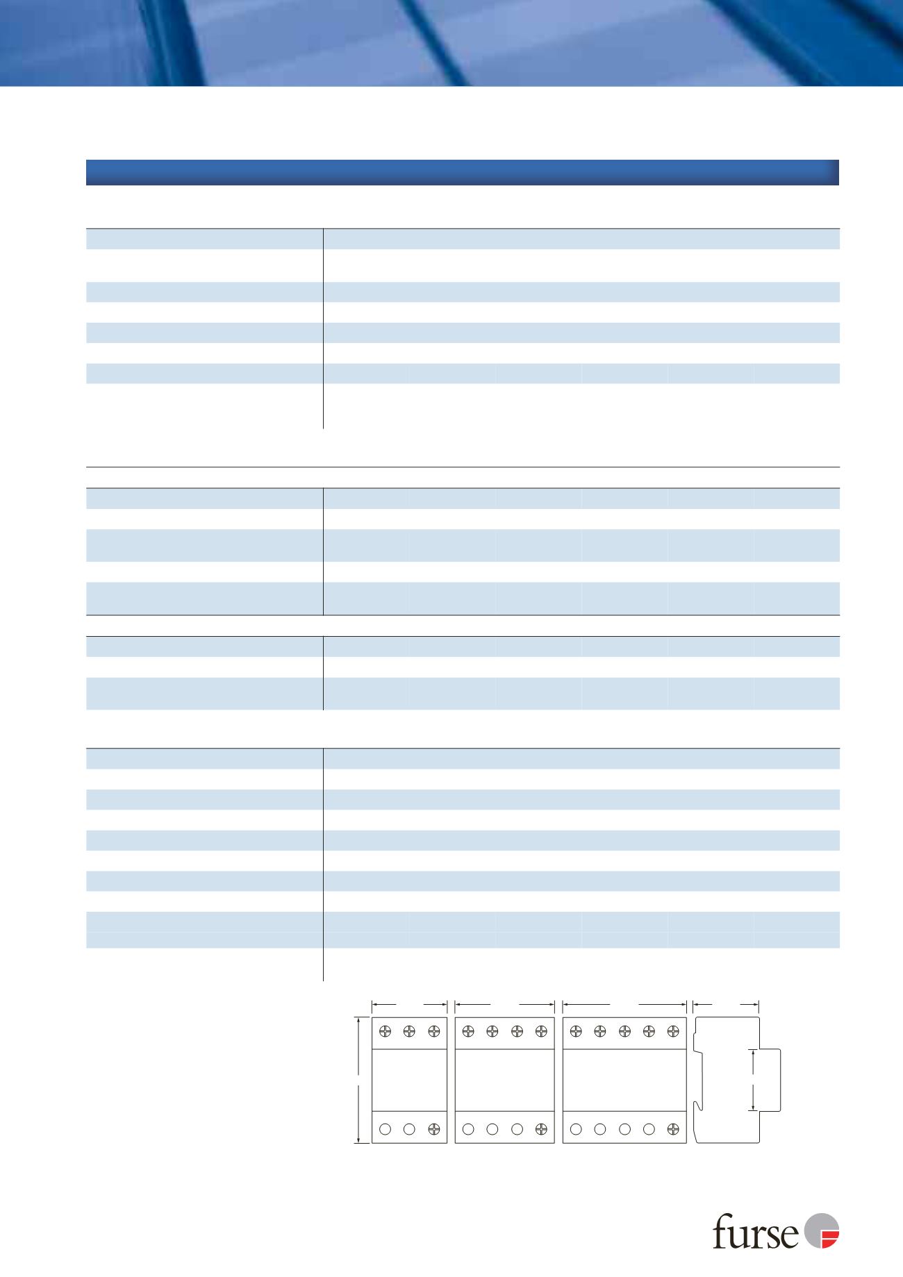
Dimensions
to DIN 43880 - HxDxW
4
90 mm x 68 mm
x 72 mm (4TE)
90 mm x 68 mm
x 72 mm (4TE)
90 mm x 68 mm
x 54 mm (3TE)
90 mm x 68 mm
x 54 mm (3TE)
90 mm x 68 mm
x 90 mm (5TE)
90 mm x 68 mm
x 72 mm (4TE)
72 mm
ESP 415/I/TNS
ESP 415/III/TNS
90 mm
ESP 415/I/TT
ESP 415/III/TT
54 mm
90 mm
ESP 415/I/TNC
ESP 415/III/TNC
45 mm
51 mm
Standard
depth
68 mm
1
Temporary Overvoltage rating is for a maximum duration
of 5 seconds tested to BS EN/EN/IEC 61643.
2
The maximum transient voltage let-through of the
protector throughout the test, phase to earth and
neutral to earth.
3
The electrical system, external to the unit, may
constrain the actual current rating achieved in a
particular installation.
4
The remote signal contact (removable) adds 10 mm
to height.
Technical specification