


 56 / 100

56
HAVELLS
SPD Coordination
Coordination of SPDs within the electrical installation is
required by both BS 7671 and BS EN 62305.
BS EN 62305 establishes that the coordinated SPD
approach to transient overvoltages requires the creation of
a series of ‘Lightning Protection Zones’ (LPZs). Within the
LPZ concept, zones are defined within a building based on
the level of risk, with each zone having successively less
exposure to transient overvoltages.
Appropriate SPDs are fitted wherever service lines cross
from one LPZ to another to create a series of SPDs whose
locations and let-through voltages are coordinated in such a
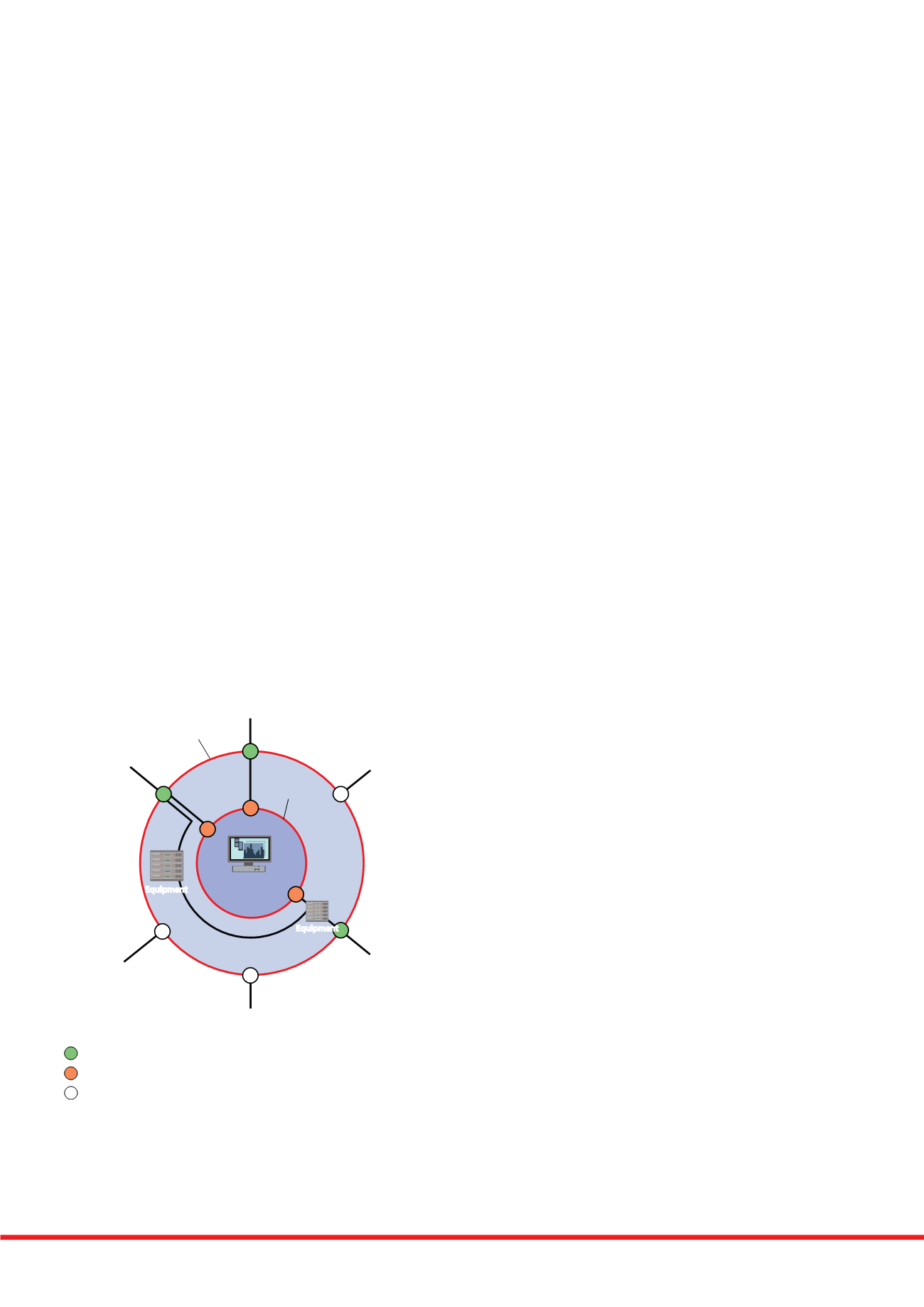
way as to ensure equipment protection. Figure 5 provides an
example of the basic LPZ concept.
For practical installation purposes on AC power lines, the
boundaries between LPZs are expected to be at the service
entrance/main distribution board, sub-distribution board and
terminal equipment levels.
Poor coordination could mean that the downstream SPDs
or terminal equipment are subject to too high a transient
overvoltage. Use of SPDs from a single manufacturer
however, as per the Havells/Furse
®
solution, will ensure SPD
coordination across all LPZs.
Boundary
of LPZ 2
(shielded room)
Boundary
of LPZ 1
(LPS)
Antenna
Electrical
power line
Water pipe
Gas pipe
Telecoms
line
Mast or
railing
LPZ 2
B
B
B
B
LPZ 1
Critical
equipment
Equipment
SPD 1/2 - Overvoltage protection
Connected service directly bonded
SPD 0/1 - Lightning current protection
Equipment
LPZ 0
Boundary
of LPZ 2
(shielded room)
Boundary
of LPZ 1
(LPS)
Antenna
Electrical
power line
Water pipe
Gas pipe
Telecoms
line
Mast or
railing
LPZ 2
B
B
B
B
LPZ 1
Critical
equipment
Equipment
SPD 1/2 - Overvoltage protection
Connected service directly bonded
SPD 0/1 - Lightning current protection
Equipment
LPZ 0
Figure 5: LPZ concept/
coordinated SPDs
LPZ 0 (outside the structure) is where
the threat of lightning currents and
fields is most severe, whereas at
LPZ 2 (within the structure) the
threat of lightning surge energy is
considerably reduced such that
electronics can be safely located
there.
A lightning current/equipotential
bonding SPD is installed at the
service entrance (LPZ boundary
0/1) to handle the majority of surge
energy, sufficiently relieving transient
overvoltage SPDs (LPZ boundary
1/2) installed downstream (typically
at sub-distribution level or local to
critical equipment) to control transient
overvoltages to safe levels.
Note: within the illustration,
2 internal zones are shown for
simplicity, although more zones
may be applicable dependent
on the installation/equipment to
be protected.
The benefits of choosing the
Havells/Furse
®
solution
Havells Type ‘A’ SPN, Type ‘B’ TPN and MCCB distribution
boards are available with Furse
®
ESP mains power SPD
kits, which can be quickly and easily installed either in
the metering section (MCCB boards) or in the enclosure
provided (Type ‘A’ SPN or Type ‘B’ TPN boards).
This innovative solution has been specifically designed and
tested to ensure optimum transient overvoltage protection on
AC power supplies, with controlled and verified installation
performance to BS 7671 and BS EN 62305.
The combined Havells distribution board and Furse
®
SPD kit
permits unrivalled specification for AC power distribution and
transient overvoltage protection, including:
s ! FULLY TESTED 30$ TO )%# #LASS ))) EQUIPMENT LEVEL TEST
providing a proven low let-through voltage of 600V on
230V AC supplies, at the SPDs terminals
s #ONTROLLED INSTALLATION BETWEEN 30$ AND DISTRIBUTION
board with supplied short length connecting leads
ensuring minimal additive inductive voltages
s )NSTALLED PERFORMANCE OF THE 30$ VERIlED IN LINE WITH THE
typical susceptibility level of equipment
s #OMBINED 4YPE
30$ PERFORMANCE FOR EFFECTIVE
protection against both flashover and transient
overvoltages
s &ULL -ODE 30$ CAPABILITY FOR PROTECTION BETWEEN ALL
conductor combinations, L-E, L-N, N-E, ensuring
continuous operation of electrical equipment
s &ULL 30$ COORDINATION ON SITE WHERE (AVELLS DISTRIBUTION
boards are installed together with Furse
®
ESP mains
power SPDs