


 19 / 28

HomeSafe Product Guide 19
Hammer trip mechanism
"TQQDMS +HLHSHMF CDRHFM HM HSRDKE L@X MNS ETKjKK SGD QDPTHQDLDMS
of quick breaking (instantaneous action) mainly due to
inertia of the Latch mechanism and interconnected
sequence of operations.
A Hammer directly connected to the plunger strikes the
moving contact arm with a force proportional to the peak
current there by forcibly separating the moving contact
EQNL SGD jWDC BNMS@BS LTBG ADENQD SGD K@SBG LDBG@MHRL
operates. This further reduces the opening time of the
circuit breaker.
Ambient temperature compensation/diversity factor chart
Effect of frequency variation
MCBs are designed to operate at AC frequency 50/60 Hz.
However, MCBs specially suitable for DC applications and
for frequencies up to 400 Hz can be supplied on request.
These can be used on different frequencies in supply from
16 2/3 - 60 Hz without any deration.
For higher frequencies, normal MCBs can be used with a
multiplication factor which shall only affect its magnetic
trip current.
Calculation
I
n
/ MCB = K
1
x K
2
x I
n
Example
4 MCBs with I
n
= 10 A, and the amb. temp.
HR " kept with no gap in between
Solution
K1 = 0.89 (from graph 1)
K2 = 0.78 (from graph 2)|
I
n
/ pole = 0.89 x 0.78 x 10 = 6.94 A
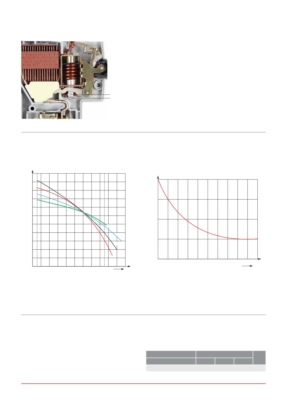
-25 -10 0 10 20 30 40 50 60
10A
6A
0.7
0.8
0.9
1.0
1.1
1.2
1.3
1.4
1.5
16-32A
40-63A
1-4A
K
Factor
Number of poles placed together with gap in between
1 2 3 4 5 6 7 8 9 10 11
0.6
0.7
0.8
0.9
1.0
Factor
Maximum Permissible Rated Current (K
1
Factor)
Graph 1
Diversity Factor (K
2
Factor)
Graph 2
K
2
K
1
Hammer
Plunger
Supply
AC
#"
Frequency
100 Hz 200 Hz 400 Hz
Multiplication Factor
1.1
1.2
1.5
1.5