


 18 / 28

18
HAVELLS
Characteristics curves
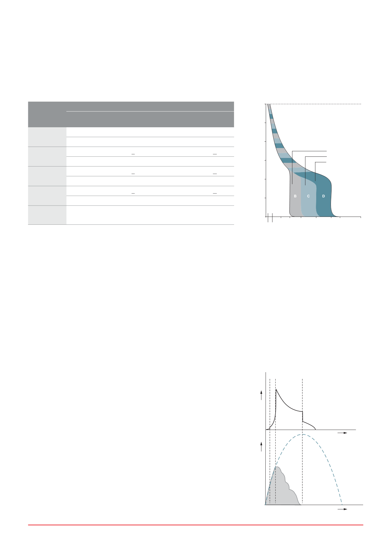
Tripping characteristics
Based on the Tripping Characteristics,
MCBs are available in ‘B’, ‘C’ and
‘D’ curve to suit different types of
applications.
‘B’ Curve:
for protection of electrical
circuits with equipment that does
not cause surge current (lighting and
distribution circuits). Short circuit release
is set to (3-5) In
‘C’ Curve:
for protection of electrical
circuits with equipment that causes
surge current (inductive loads and
motor circuits).
Short circuit release is set to (5 - 10) In
?# "TQUD
for protection of electrical
circuits which causes high inrush
current, typically 12-15 times the
thermal rated current (transformers,
X-ray machines etc.) Short circuit
release is set to (10 - 20) In
Voltage across contacts
during opening of MCB
Maximum
Prospective
Fault
Current
Time
Current
Voltage
A
B
0
0 t
x
t
1
t
2
Multiples of Rated Current (x I
n
)
Time (sec.)
10000.00
1000.00
100.00
10.00
1.00
0.10
0.01
1
2 3 5
10
20 30
100
1.13 1.45
B Curve
C Curve
D Curve
As per
Thermal Tripping
Magnetic Tripping
No
tripping Tripping Time Hold Trip Time
IS / IEC
60898-1
Current Current
Limits Current Current
Limits
I
1
I
2
t
I
4
I
5
t
B Curve
1.13 x I
n
>1h
3 x I
n
>0.1s
1.45 x I
n
<1h
5 x I
n
<0.1s
C Curve
1.13 x I
n
>1h
5 x I
n
>0.1s
1.45 x I
n
<1h
10 x I
n
<0.1s
D Curve
1.13 x I
n
>1h 10 x I
n
>0.1s
1.45 x I
n
<1h
20 x I
n
<0.1s
l
3
= 2.55 x l
N
1s < t < 60s for l
n
< 32 A
1s < t < 120s for l
n
> 32 A
MCB
* s = second
Current limiting design
In a current limiting breaker, the tripping & arc control mechanism are designed
so that under short circuit conditions, the contacts are physically separated and
the electrodynamic forces generated by fault current, assist with the extinction
in less than half cycle.
3GD jFTQD RGNVR SGD BTQQDMS KHLHSHMF DEEDBS NE BHQBTHS AQD@JDQR
Fault Traces for Voltage & Current
0 = Point of fault initiation
t
x
= Contact opening time (i.e. creation of arc)
t
1
= Current / Voltage peak (i.e. current limitation)
t
2
= Time to total extinction of arc (i.e. complete shutdown of fault current)