


 169 / 180

169
Technical
information
Wiring accessories
Rotary and 2 way (push) dimmers
Circuits
n
Only use two-way (push) dimmers in two-way switching circuits. Only use one two-way dimmer in a two-way switching circuit.
Lamps
n
These dimmer switches are suitable for dimming incandescent lamps and dimmable CFL lamps only and are NOT to be used with
Fluorescent lamps, Light Emitting Diode (LED) lamps of any description or motor loads. Use of non-dimmable CFL lamps may permanently
damage the dimmer or the lamp and will invalidate any guarantee or warranty supplied with the dimmer switch.
n
It is recommended that a maximum number of 5 dimming CFL lamps only should be connected to an individual dimmer switch.
Dimmable low voltage transformers
n
Only use Low Voltage dimmers with transformers. Do not use mains voltage dimmers.
n
The Low Voltage dimmer switches use leading edge (phase delay) dimming technology and must therefore be used with compatible good
quality dimmable electronic or wire-wound transformers. Trailing edge (phase cut) dimmable transformers must not be used.
Co-Axial and Satellite sockets
Non isolated
Non-isolated products are intended for direct connection to a single or two separate TV/FM aerial downleads. These units are not designed
for use in multi outlet systems.
Single TV/FM outlet for connection to a single TV or FM coaxial aerial lead.
Twin outlet for connection to each of two separate TV/FM, coaxial aerial leads.
Diplex and Triplex
Performance
Diplex
TV/FM diplex units for connection to a single coaxial aerial lead with combined TV and FM signals.
The connector standard IEC 169-2 plug for TV and IEC 169-2 socket for Radio.
Triplex
TV/FM/SAT triplex unit for connection to a single coaxial aerial lead with combined TV, FM and satellite signals.
TV: 470-860MHZ
Radio: (FM) 87.5 – 108 MHz and (DAB) 217.5 – 230 MHz.
Satellite: DC – 200kHz and 950-2300MHz.
The connector standard is ‘f’ for satellite, IEC 169-2 plug for TV and IEC 169-2 socket for Radio.
Telephone socket outlets
It is legal for a contractor to install a secondary telephone socket with associated wiring into house-holds with single exchange lines. The
contractor may install a secondary socket and wire up to the master socket and wiring to the exchange. This does not include wiring the
actual master socket or to the exchange itself. this final connection must be made by an approved installer.
For commercial and industrial installations a PBX (or PABX) internal exchange or ‘intelligent’ telephones are often fitted. In this case, the
contractor may install all of the equipment except for the PBX unit installation. Again this must be carried out by a BSI approved installer and
the interface between the PBX/PABX internal system and the incoming external lines must be connected by British Telecom.
Schneider Electric telephone sockets are suitable for use in accordance with BS 7671, formerly the 16th Edition of the IEE Wiring regulations
and should be wired in accordance with the diagrams shown.
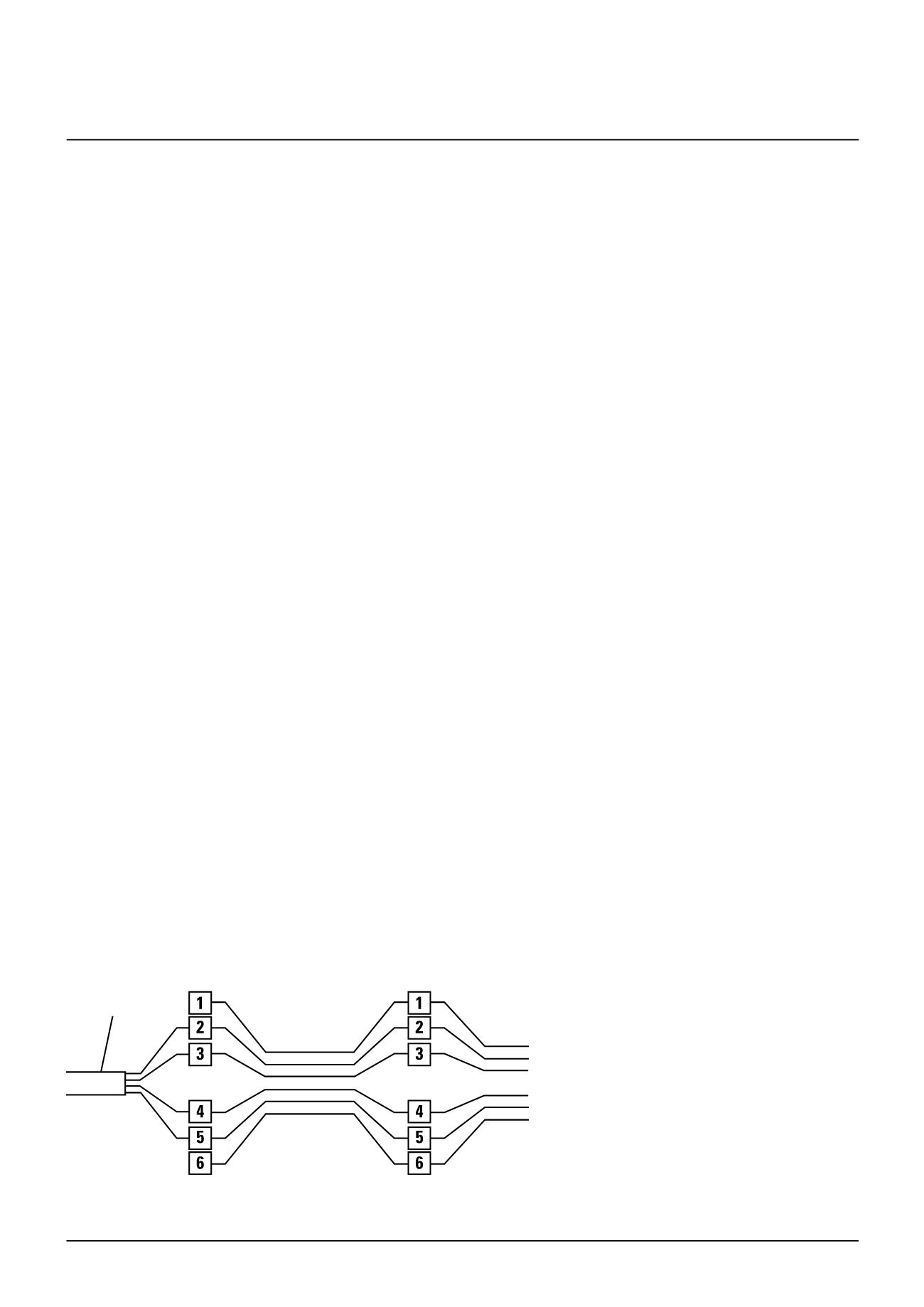
Existing incoming
cable from PBX etc
.
1st socket outlet
(single master)
Additional socket outlet(s)
(single secondary)
Example of typical connection
1 Connection to 2 & 5
2 Earth recall (when used) connect to terminal 4
3 Connection to terminal 3 is not usually required
NB
(a) Standard 4 wire cable is shown below as incoming cable. If terminals 1 and 6 (normally unused) are required, 6 wire cable may be used.
(b) All socket outlet connections are parallel – any number of socket outlets can be connected, but it is recommended that only a maximum
of 5 telephones be used at any one time on one line.