


 168 / 180

168
Technical
information
Wiring accessories
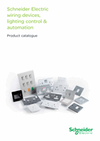
IMPORTANT NOTES -
for 1 Way Installation
1. Read General Installation Safety Instructions
before starting work
2. Do not connect any conductor to dimmer terminal
marked RS. This is for use with 2 way switching
1 way installation wiring diagram
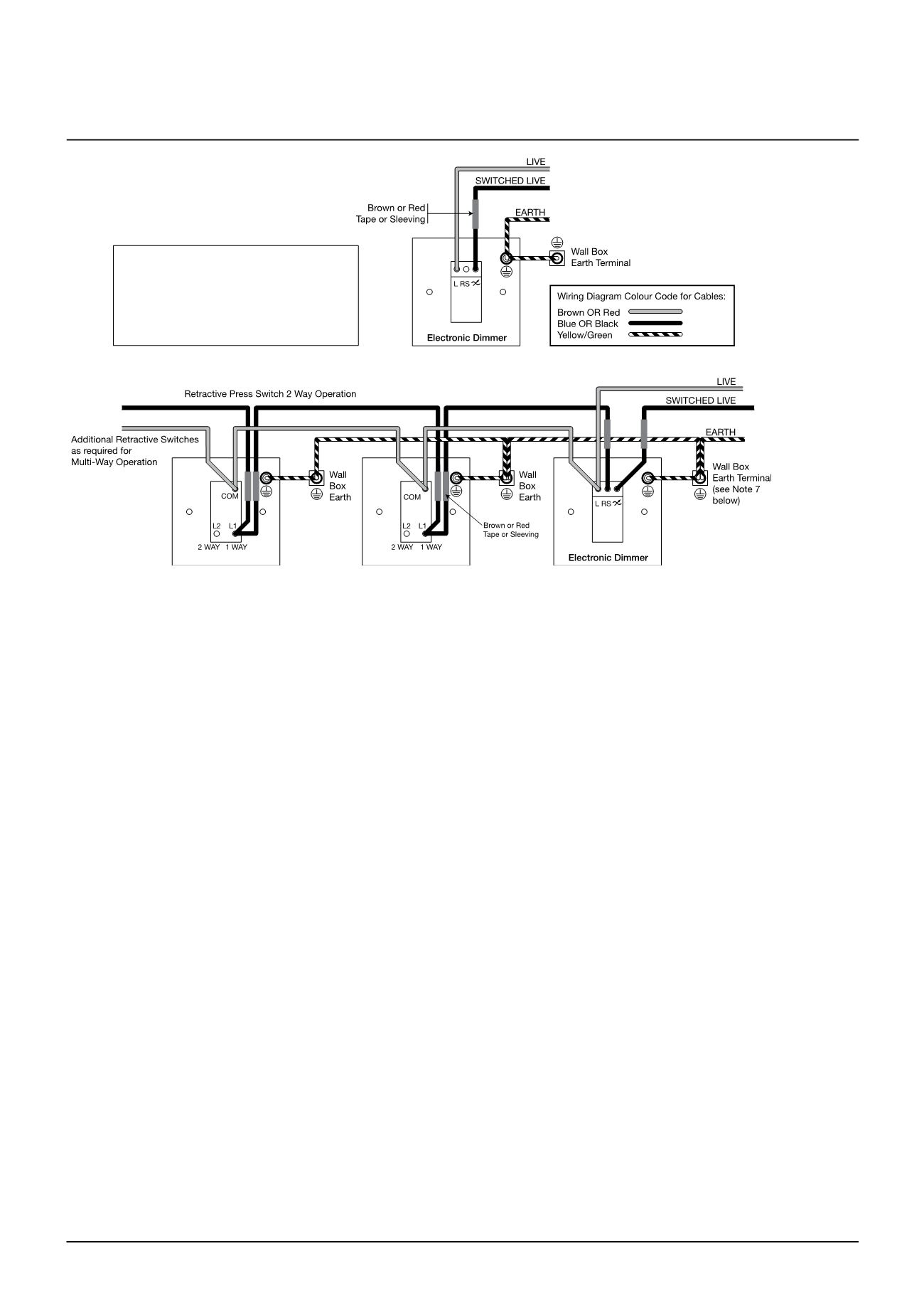
2 way and multi-way installation wiring diagram
Important notes
- for two way and multi - way installation
1. Read General Installation Safety Instructions before starting work.
2. Any existing 2 Way or Intermediate switches MUST be replaced with Retractive Press Switches.
3. Any number of Retractive Press Switches may be installed provided total cable length does not exceed 50m.
4. Either 1 Way normally open or 2 Way Retractive Push Switches may be used.
5. If 2 Way retractive switches are used, connect to Common (COM) and normally open L1 (1 WAY) terminals as shown. Do NOT use the L2
(2 WAY) terminal.
6. If replacing an existing 2 Way switch,cut back and insulate the unused 2 way wire previously connected to the L2 (2 way) terminal.
7. All Metal Wall Boxes and Metal Plate Switches must be earthed.
8. Do NOT connect more than 1 Dimmer in the same circuit,
9. Remove label covering centre terminal on rear of dimmer. This terminal is to be connected to Retractive Switch as shown in wiring
diagram. Do NOT connect any other conductor to this terminal.
Circuit, lamp and other equipment compatibility
To ensure optimum performance and reliability is obtained from dimmer switches the following recommendations and precautions should be
followed as appropriate to the type of dimmer:
General recommendations
Circuits
It is recommended that all lighting circuits incorporating dimmers be protected by a 6A or up to a 10A maximum Type B miniature circuit breaker.
Tungsten halogen lamps
When using mains voltage Tungsten Halogen lamps, it is essential that these types of lamp incorporate internal fuses or are constructed such
that arcing at the end of life cannot occur and are from quality lamp manufacturers. The use of inferior low quality lamps is not recommended
and will invalidate any guarantee or warranty supplied with the dimmer switch.
Dimmable low voltage transformers
n
Always check transformer compatibility BEFORE installation and if in doubt always check with the dimmer Helpline or the transformer
manufacturer. It is recommended that electronic dimmable transformers be loaded to at least 70% of their rated maximum wattage.
n
When running multiple lamps on dimmable electronic transformers ensure that all lamps are working correctly. Replace failed lamps as
soon as possible as a single failed lamp may cause flickering of all other lamps connected to the same dimmer.
n
Do NOT mix electronic and magnetic transformers on the same dimmer switch.
n
It is recommended that a maximum number of 5 Low Voltage transformers only should be connected to an individual dimmer switch.
Electronic dimmers
Circuits
n
For two-way or more switching ONLY use retractive switches. Do NOT use two-way switches.
n
The live supply for retractive switches must come from the live (L) connection of the dimmer.
Lamps
n
Do NOT use with Compact Fluorescent Lamps (CFL) even if marked “dimmable”, Fluorescent lamps and Light Emitting Diode (LED) lamps
of any description or motor loads.
Dimmable low voltage transformers
n
These Electronic dimmer switches, except the 1kW, use leading edge (phase delay) dimming technology and must therefore be used with
compatible good quality dimmable electronic or wire-wound (magnetic) transformers. Trailing edge (phase cut) dimmable transformers
must not be used.
n
The 1kW dimmer switch uses trailing edge (phase cut) dimming technology and must therefore be used with compatible good quality
dimmable electronic transformers. Do not use the 1kW dimmer with magnetic transformers.