


 57 / 73

56
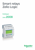
Connections
1
Connection schemes for connecting communication interface SR2 COM01 to the smart relay and the
Modem
SR
p
B
pp
1JD, SR
p
B
ppp
BD and SR2 E
ppp
BD
(1)
(2)
(4)
+
12-24VDC
SR2 COM01
COM-M
COM-Z
STATUS
+
I1 I2 I3 I4 I5 I6 IBIC
Q1 Q2 Q3 Q4
(3)
COM-M
–
+
(1)
c
12 or 24 V
Input
connections
Output
connections
SR2 MOD01
or
SR2 MOD02
(1) 1 A quick-blow fuse.
(2) Cable included with Modem communication interface SR2 COM01.
(3) Cable for connection to the Transmission network (included with analogue PSTN modem).
(4) Antenna included with GSM modem.
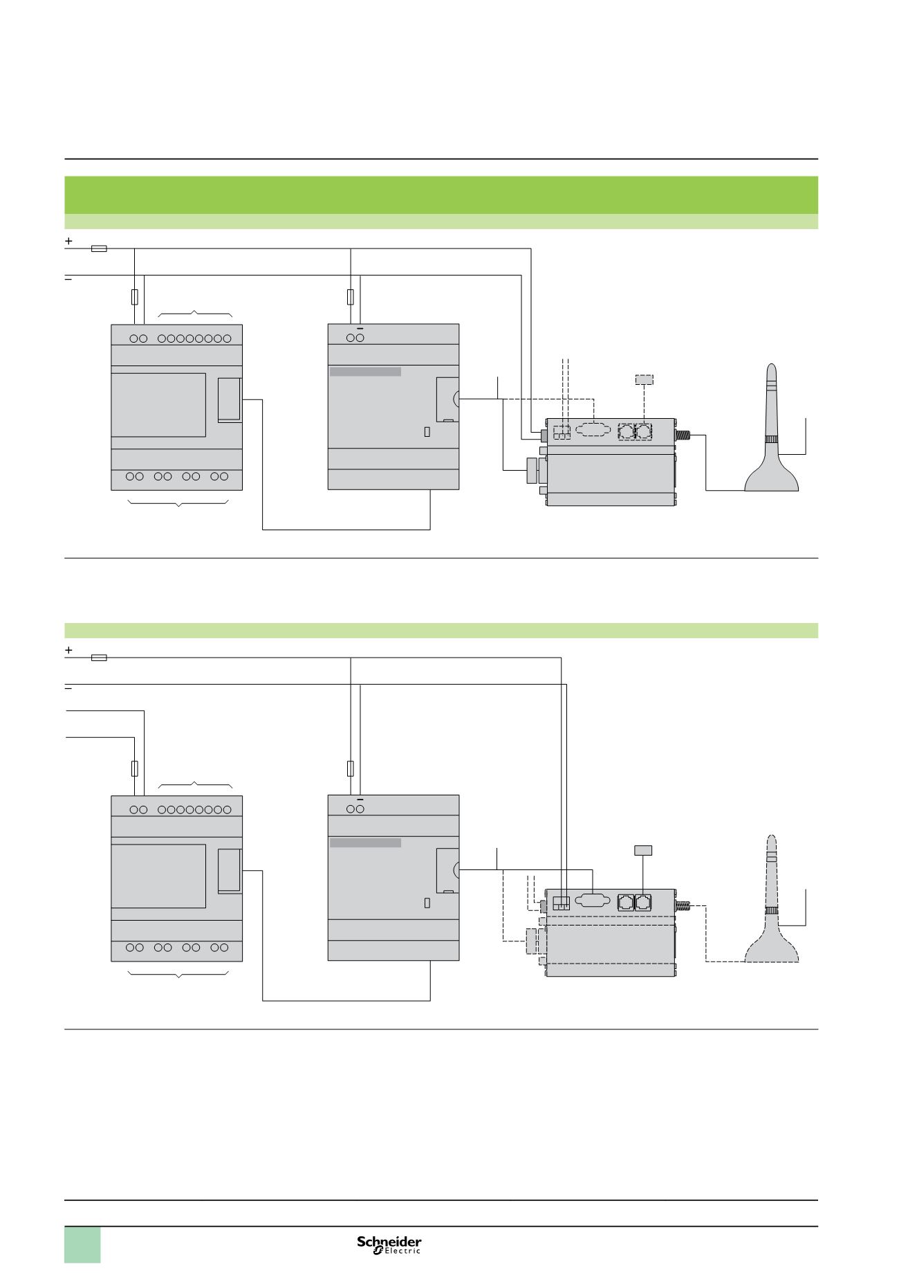
SR
p
B
pp
1B, SR
p
B
ppp
FU, SR2 E
ppp
B and SR2 E
ppp
FU
c
12…24 V
Input
connections
Output
connections
SR2 MOD01
or
SR2 MOD02
(1)
(3)
(2)
(4)
+
12-24VDC
SR2 COM01
COM-M
COM-Z
STATUS
+
I1 I2 I3 I4 I5 I6 IBIC
Q1 Q2 Q3 Q4
–
+
(1)
a
24 V or
a
100…240 V
(1) 1 A quick-blow fuse.
(2) Cable included with Modem communication interface SR2 COM01.
(3) Cable for connection to the Transmission network (included with analogue PSTN modem).
(4) Antenna included with GSM modem.
Presentation, description :
pages 48 and 49
Functions, setting-up
pages 50 and 51
Characteristics :
pages 52 and 53
References :
page 54
Dimensions :
pages 55
Zelio Logic smart relays
1
Modem communication interface
1
2
3
4
5
6
7
8
9
10