
51
Smart relay
Functions
(continued),
setting up
1
Functions available depending on the hardware architecture and/or type of SIM card
Function
Remote
station device
Analogue PSTN
Modem
GSM Modem
Type of SIM card
DATA
DATA VOICE
VOICE
DATA N°
VOICE N°
Send alarm/receive instruction with GSM telephone
Send alarm/receive instruction with PC
running “Zelio Logic Alarm” software
(1)
Transfer program
Update firmware Monitoring
(1)
Send alarm to e-mail address
Functions available
Functions not available
Note:
Instructions cannot be transmitted by e-mail.
(1) When using a GSM Modem on the PC side, the SIM card must have a DATA number.
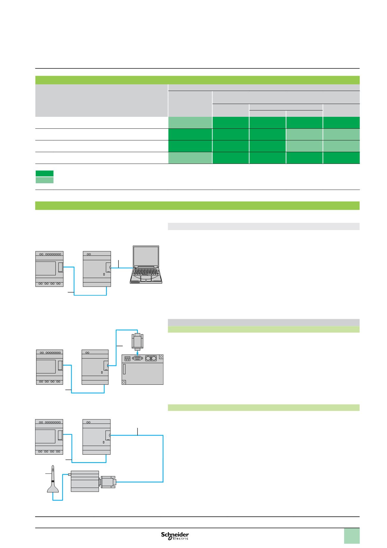
Installation set-up
Setting-up of the installation or the machine to be monitored involves 2 steps:
Connection for programming the smart relay and the interface
1
Interface cable
marked COM-Z.
2
Cable SR2 USB01 or SR2 CBL01.
After having powered-up the smart relay and the interface, the application program
can be transferred in order to simultaneously:
load the automation system program into the smart relay,
load the alarm conditions, messages and telephone numbers/e-mail addresses
into the interface.
This operation can also be carried out remotely using “Transfer” mode, after having
made the operating connections described below.
d
Program loading using memory cartridges SR2 MEM01 or SR2 MEM02 is
incompatible with Modem communication interface SR2 COM01.
Operating connections
PSTN analogue modem
1
Interface cable marked COM-Z.
2
Cable SR2 CBL07 included with the interface.
GSM Modem
1
Interface cable marked COM-Z.
2
Cable SR2 CBL07 included with the interface.
3
Antenna and cable included with the Modem.
b
b
SR2 COM01
1
2
Smart relay
Communication
interface
PC
SR2 COM01
1
2
SR2 MOD01
Smart relay
Communication
interface
Analogue PSTN Modem
SR2 COM01
1
2
3
SR2 MOD02
Communication
interface
GSM Modem
Presentation, description :
pages 48 and 49
Characteristics :
pages 52 and 53
References :
page 54
Dimensions :
page 55
Connections :
pages 56 and 57
Zelio Logic smart relays
1
Modem communication interface
Smart relay
1
2
3
4
5
6
7
8
9
10


