


 47 / 413

3/5
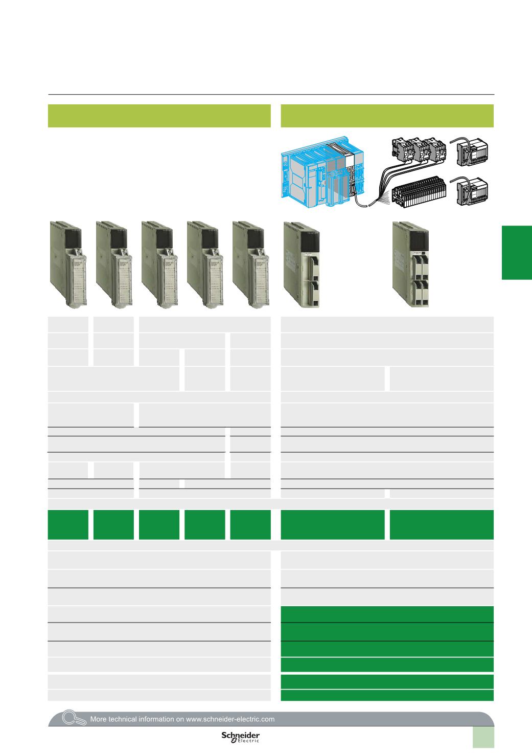
Connecting outputs to screw terminal blocks for bare wires, wires fitted
with either cable ends or open/closed cable tags
Connecting outputs to HE 10 connectors with preformed cables with
flying leads, rolled ribbon cables or multicore cables
c
or
a
relay
c
relay
a
triac
c
transistor
24…48
V
c
24…240
V
a
24…120
V 48…240 V
24…120
V
24
V
c
5
A (lth)
5
A (lth)
2
A per
channel
1
A per
channel
1
A per
channel
0.1
A per channel
8
protected channels
16
protected
channels
16
non-
protected
channels
32
protected channels
64
protected channels
Via 20-way screw terminal blocks: TSX BLY 01
Via 20-way HE 10 connector
Configurable output fallback –
Configurable output fallback, continuous monitoring of output control and
output reset in case of internal fault
Yes
Yes
Yes
Protected
Not
protected
Protected
–
–
Positive
19...60
V
c
20...264
V
a
19...143
V
c
41...264
V
a
24...132
V
a
19...30
V
c
,
possible up to 34 V
c
limited to 1 hour in every 24 hours
–
2
A
1
A
0.1
A
–
12
A
3.2
A
5
A
See page 9/6
TSX DSY
08
R5A
TSX DSY
08
R4D
TSX DSY
08
S5
TSX DSY
16
S5
TSX DSY
16
S4
TSX DSY 32T2K
TSX DSY 64T2K
3/10
–
LU9 G02 splitter box (see page 3/22)
–
8
or 16-channel passive sub-bases, with or without LED, with common or
2
terminals per channel
–
16-
channel active sub-bases with relays (1 “NO”, 1 or 2 “C/O”) or transistor
(5…48
V
c
, 24
V
c
, 24…240
V
a
), 2
terminals per channel
–
ABE 7H08R
pp
,
ABE 7H08S21
–
ABE 7H16S21
–
ABE 7H16F43
–
ABE 7S08S2
pp
,
ABE 7R08S
ppp
,
ABE 7S16S
ppp
,
ABE 7R16S
ppp
–
ABE 7P08T330, ABE 7R16T
ppp
,
ABE 7P16T
ppp
–
TSX CDP
pp
3
or ABF H20
pp
0
2
1
3
4
5
6
7
8
9
10