


 44 / 356

42
The object of standard IEC 60439-1
is to lay down the definitions and to state the
service conditions, construction requirements, technical characteristics and tests for
low-voltage switchgear and controlgear assemblies (U < 1000 V).
All elements making up the electrical switchboard are concerned.
Note.
The standard defines a low-voltage assembly (the electrical switchboard) as "a
combination of one or more low-voltage switching devices together with associated control,
measuring, signalling, protective, regulating equipment, etc., completely assembled under the
responsibility of the manufacturer with all the internal electrical and mechanical inter-connections
and structural parts".
PD390917
Standard IEC 60439-1 defines ten mandatory tests
7 type tests carried out on typical configurations
no. 1 - temperature rise limits
no. 2 - dielectric properties
no. 3 - short-circuit withstand strength
no. 4 - effectiveness of the protective circuit
no. 5 - clearances and creepage distances
no. 6 - mechanical operation
no. 7 - degree of protection.
3 routine tests carried out on the finished switchboard (their purpose is to check
that the characteristics validated by the type tests were not altered during
manufacturing operations):
no. 8 - wiring and electrical operation
no. 9 - insulation/dielectric test
no. 10 - protective measures.
b
v
v
v
v
v
v
v
b
v
v
v
7 type tests
1 - Temperature-rise limits
Each device is loaded to its rated current, multiplied by the diversity factor. Once the
temperature has stabilised, the temperature rise must not exceed the permissible
temperatures for materials or risk causing burns:
70 K for terminals for external insulated conductors
15 K or 25 K , according to material type, for manual operating means
30 K or 40 K for access ble external enclosures and covers.
2 - Dielectric properties
The test voltage is applied between all live parts and the interconnected exposed
conductive parts, as well as between each pole and all the other poles connected for
this test to the interconnected exposed conductive parts.
3500 V for a rated insulation voltage of 1000 V for busbars in cubicles and rear
busbars in enclosures
750 V for a rated insulation voltage of 3000 V according to the type of busbars in
the enclosure
500 V for a rated insulation voltage of 2500 V according to the type of busbars in
the enclosure
test duration: 1 minute.
b
b
b
b
PD391285
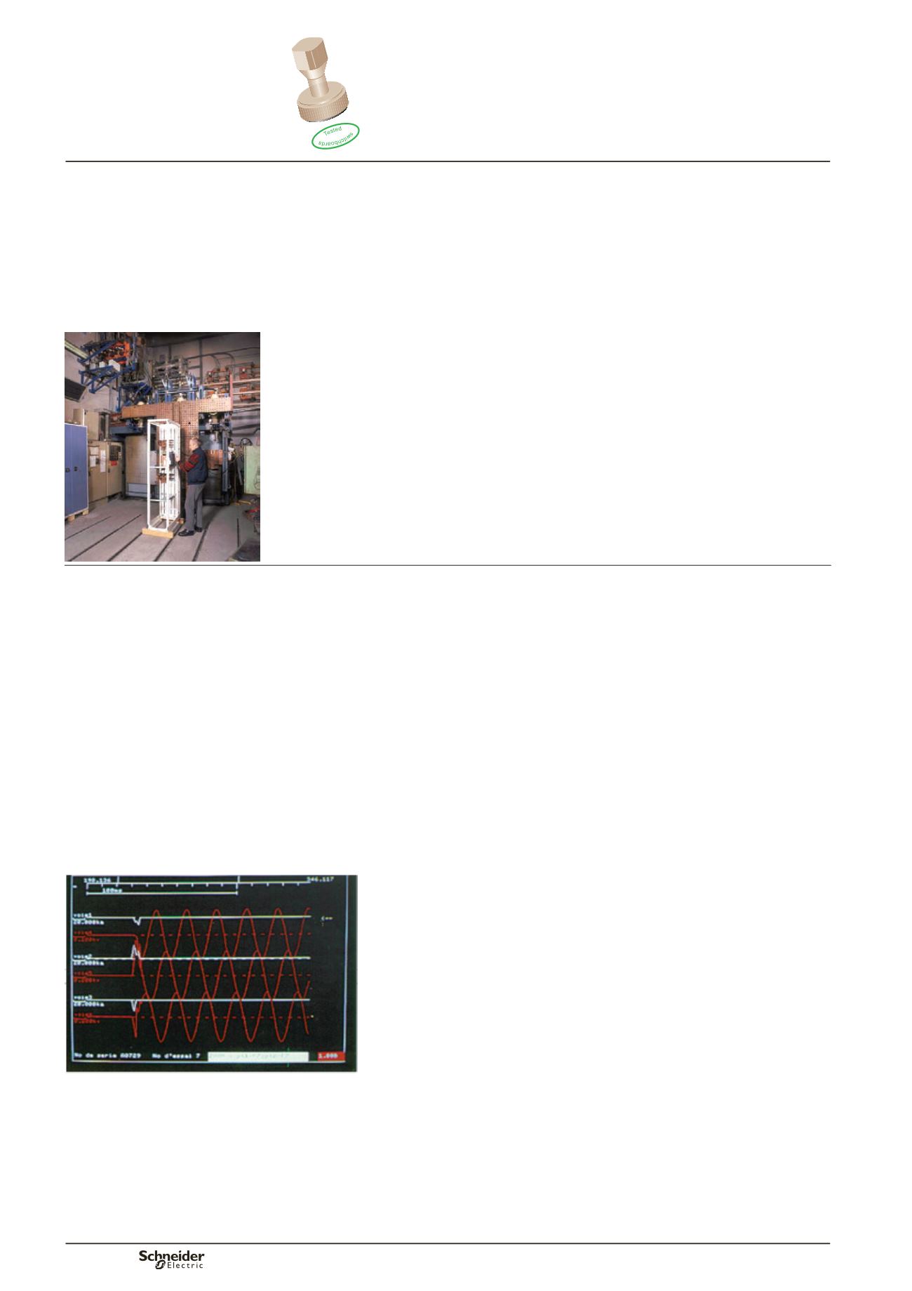
3 - Short-circuit withstand strength
In the event of a short-circuit, whether inside or outside the switchboard, the latter
must handle the resulting constraints (temperature rise, attraction or repulsion forces
exerted on conductors, etc.).
The capacity to handle the constraints is above all the means to avoid danger
(rupture and projection of components, electric arcs and their propagation outside
the switchboard).
However, it is also the means to ensure a rapid return to operation after the incident.
Maximum rated short-time current obtained on the busbars: Icw 85 kA rms/1 s.
4 - Effectiveness of the protective circuit
The effectiveness of the protective circuit is verified by two tests :
short-circuit withstand test carried out between the protective conductor and the
nearest phase conductor
resistance measurement of the connection between the exposed conductive parts
and the protective circuit.
Result: 51 kA rms.
b
b
Short-circuit withstand strength
.
Prisma Plus
tested switchboards
Standards and
Prisma Plus tested
switchboards