


 96 / 182

B-7
Installation
recommendations
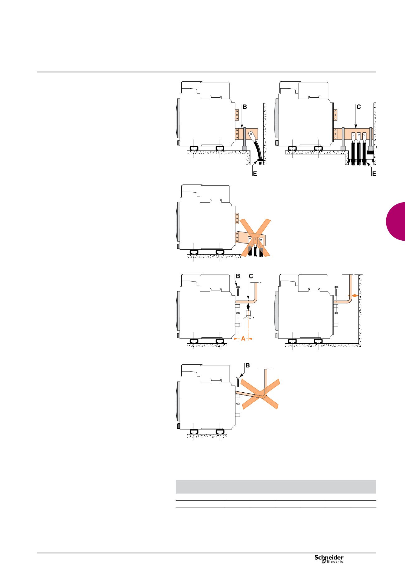
Cables connections
If cables are used for the power connections, make
sure that they do not apply excessive mechanical
forces to the circuit breaker terminals.
For this, make the connections as follows:
extend the circuit breaker terminals using short bars
b
b
designed and installed according to the
recommendations for bar-type power connections:
for a single cable, use solution
v
v
B
opposite
for multiple cables, use solution
v
v
C
opposite
in all cases, follow the general rules for connections
b
b
to busbars:
position the cable lugs before inserting the bolts
v
v
the cables should firmly secured to the framework
v
v
E
.
DB101448
DB101449
DB101450
Busbars connections
The busbars should be suitably adjusted to ensure that
the connection points are positioned on the terminals
before the bolts are inserted
B
The connections are held by the support which is solidly
fixed to the framework of the switchboard, such that the
circuit breaker terminals do not have to support its
weight
C
. (This support should be placed close to the
terminals).
DB101451
DB101452
DB101453
Electrodynamic stresses
The first busbar support or spacer shall be situated within a maximum distance from
the connection point of the breaker (see table below). This distance must be
respected so that the connection can withstand the electrodynamic stresses
between phases in the event of a short circuit.
Maximum distance A between busbar to circuit breaker connection and the first busbar
support or spacer with respect to the value of the prospective short-circuit current.
Isc (kA)
30
50
65
80
100
150
Distance A (mm)
350
300
250
150
150
150
Power connection
version: 8.3
207E3300.indd