


 100 / 182

B-11
Installation
recommendations
Basis of tables:
maximum permissible busbars temperature: 100 °C
b
b
Ti: temperature around the circuit breaker and its
b
b
connection
busbar material is unpainted copper.
b
b
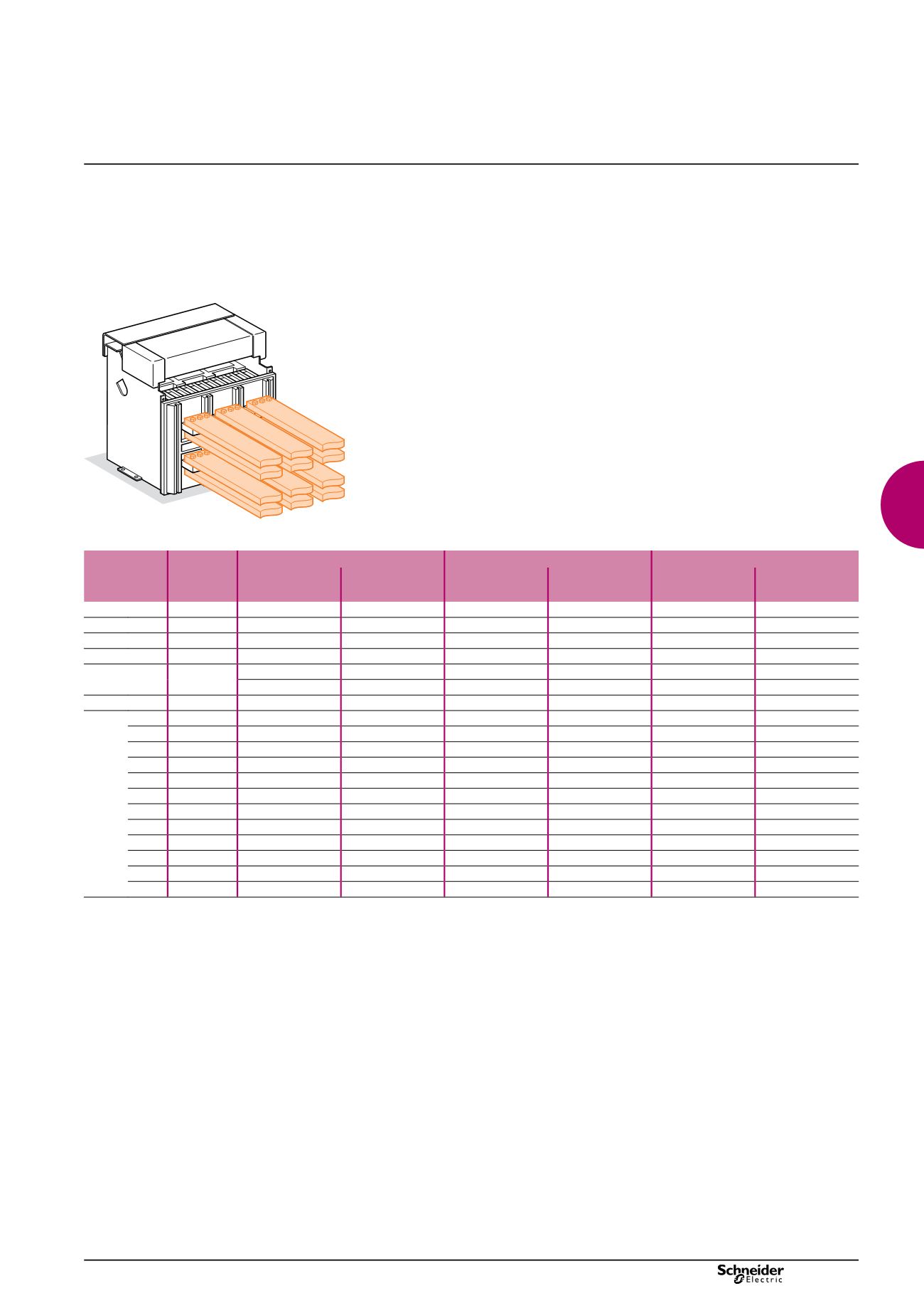
Front or rear horizontal connection
DB101484
Masterpact Maximum
service
current
Ti : 40 °C
Ti : 50 °C
Ti : 60 °C
No. of 5 mm
thick bars
No. of 10 mm
thick bars
No. of 5 mm
thick bars
No. of 10 mm
thick bars
No. of 5 mm
thick bars
No. of 10 mm
thick bars
NT06
400
2b.30 x 5
1b.30 x 10
2b.30 x 5
1b.30 x 10
2b.30 x 5
1b.30 x 10
NT06
630
2b.40 x 5
1b.40 x 10
2b.40 x 5
1b.40 x 10
2b.40 x 5
1b.40 x 10
NT08 ou NW08 800
2b.50 x 5
1b.50 x 10
2b.50 x 5
1b.50 x 10
2b.50 x 5
1b.63 x 10
NT10 ou NW10 1000
3b.50 x 5
1b.63 x 10
3b.50 x 5
2b.50 x 10
3b.63 x 5
2b.50 x 10
NT12 ou NW12 1250
3b.50 x 5
2b.40 x 10
3b.50 x 5
2b.50 x 10
3b.63 x 5
2b.50 x 10
2b.80 x 5
2b.40 x 10
2b.80 x 5
NT16 ou NW16 1400
3b.63 x 5
2b.40 x 10
3b.63 x 5
2b.50 x 10
3b.80 x 5
2b.63 x 10
NT16 ou NW16 1600
3b.80 x 5
2b.63 x 10
3b.80 x 5
2b.63 x 10
3b.80 x 5
3b.50 x 10
NW20 1800
3b.80 x 5
2b.63 x 10
3b.80 x 5
2b.63 x 10
3b.100 x 5
2b.80 x 10
NW20 2000
3b.100 x 5
2b.80 x 10
3b.100 x 5
2b.80 x 10
3b.100 x 5
3b.63 x 10
NW25 2200
4b.100 x 5
2b.80 x 10
4b.100 x 5
2b.80 x 10
4b.100 x 5
2b.100 x 10
NW25 2500
4b.100 x 5
2b.100 x 10
4b.100 x 5
2b.100 x 10
4b.100 x 5
3b.80 x 10
NW32 2800
4b.100 x 5
3b.80 x 10
4b.100 x 5
3b.80 x 10
5b.100 x 5
3b.100 x 10
NW32 3000
5b.100 x 5
3b.80 x 10
6b.100 x 5
3b.100 x 10
8b.100 x 5
4b.80 x 10
NW32 3200
6b.100 x 5
3b.100 x 10
8b.100 x 5
3b.100 x 10
4b.100 x 10
NW40 3800
4b.100 x 10
5b.100 x 10
5b.100 x 10
NW40 4000
5b.100 x 10
5b.100 x 10
6b.100 x 10
NW50 4500
6b.100 x 10
6b.100 x 10
7b.100 x 10
NW50 5000
7b.100 x 10
7b.100 x 10
With Masterpact NT, it is recommanded to use 50 mm wideness bars (see “Recommended busbars drilling”).
Example
Conditions:
drawout version
b
b
horizontal busbars
b
b
Tb
b
i
: 50 °C
service current: 1800 A.
b
b
Solution:
For T
i
= 50 °C, use an NW20 which can be connected
with three 80 x 5 mm bars or two 63 x 10 mm bars.
Note:
the values indicated in these tables have been extrapolated from test data and theoretical
calculations. These tables are only intended as a guide and cannot replace industrial experience
or a temperature rise test.
Busbar sizing
version: 8.3
207E3300.indd