


 103 / 182

B-14
Factors affecting switchboard design
The temperature around the circuit breaker and its
connections:
This is used to define the type of circuit breaker to be
used and its connection arrangement.
Vents at the top and bottom of the cubicles:
Vents considerably reduce the temperature inside the
switchboard, but must be designed so as to respect the
degree of protection provided by the enclosure.
For weatherproof heavy-duty cubicles, a forced
ventilation system may be required.
The heat dissipated by the devices installed in the
switchboard:
This is the heat dissipated by the circuit breakers under
normal conditions (service current).
The size of the enclosure:
This determines the volume for cooling calculations.
Switchboard installation mode:
Free-standing, against a wall, etc.
Horizontal partitions:
Partitions can obstruct air circulation within the
enclosure.
Basis of tables
switchboard dimensions
b
b
b
number of circuit-breakers installed
b
type of breaker connections
b
drawout versions
b
ambient temperature outside of the switchboard: T
a
(IEC 60439-1).
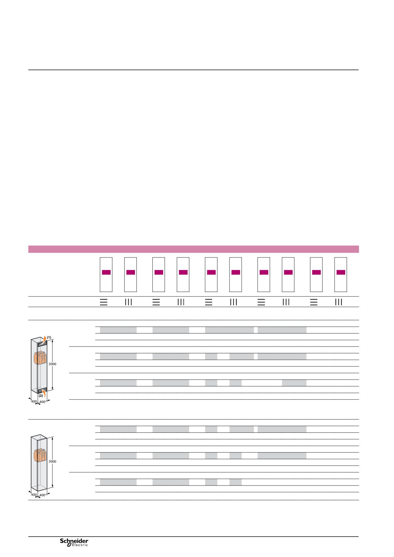
Masterpact NT06-16 H1/H2/L1
(switchboard 2000 x 400 x 400) - area of outlet vents: 150 cm
2
Type
NT06 H1/H2/L1
NT08 H1/H2/L1
NT10 H1/H2/L1
NT12 H1/H2
NT16 H1/H2
Switchboard composition
4
3
2
1
Connection type
Busbar dimensions (mm)
2b. 40 x 5
2b. 50 x 5
3b. 63 x 5
3b. 63 x 5
3b. 80 x 5
3b. 50 x 5
3b. 63 x 5
Ventilated switchboard
(
➨
IP31)
4
H1/L1 H1/L1
DB108437
3
630
630
800
800
1000/1000 1000/1000 1250
1250
1400
1520
T
a
= 35 °C 2
1
T
a
= 45 °C
4
3
630
630
800
800
1000/950 1000/1000 1250
1250
1330
1440
2
1
T
a
= 55 °C
4
3
630
630
800
800
1000/890 1000/960 1200
1250
1250
1340
2
1
(1)
Area of outlet vents: 150 cm².
(2)
Area of intlet vents: 150 cm².
Non ventilated switchboard
(
➨
IP54)
4
DB101495
3
630
630
800
800
1000/960 1000/1000 1250
1250
1330
1400
T
a
= 35 °C 2
1
T
a
= 45 °C
4
3
630
630
800
800
1000/910 1000/980 1220
1250
1260
1330
2
1
T
a
= 55 °C
4
3
630
630
800
800
1000/860 1000/930 1150
1230
1200
1260
2
1
Note:
the values indicated in these tables have been extrapolated from test data and theoretical calculations. These tables are only intended as a guide and cannot
replace industrial experience or a temperature rise test.
The values indicated for the cross-sectional area of the vents should be considered as general indications only given that the thermal performance of a switchboard
with natural ventilation depends on many parameters, e.g. shape, porosity and location of vents and air flow within the switchboard.
Derating in switchboards
version: 8.3
207E3300.indd