


 159 / 182

D-18
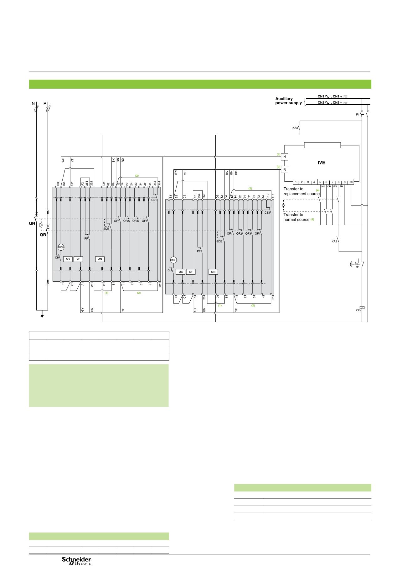
Electrical diagrams
Electrical interlocking by IVE unit with lockout after a fault and emergency off by undervoltage release
DB401822
ATTENTION
(1)
Not to be wired for the “without lockout after a fault” solution.
(2)
Not to be wired on fixed version.
(3)
Prefabricated wiring supplied.
(4)
See section “IMPORTANT” here after.
The diagram shows the electrical wiring for circuit breakers.
When wiring the SDE with
switch-disconnectors, connect
wire BK to terminal 82.
IMPORTANT
The relays controlling the “normal” and “replacement”
circuit breakers must be mechanically and/or
electrically interlocked to prevent them from giving
simultaneous closing commands.
Legends
QN
“Normal” source Masterpact NT or NW
QR
“Replacement” source Masterpact NT or NW
MCH
spring-charging motor
MX
standard opening voltage release
XF
standard closing voltage release
MN
undervoltage release
OF...
breaker ON/OFF indication contact
SDE1
“fault-trip” indication contact
PF
“ready-to-close” contact
CE1
“connected-position” indication contact (carriage switch)
CH
“springs charged” indication contact
IVE
electrical interlocking and terminal block unit
F1
auxiliary power supply circuit breaker
BP
emergency off button with latching
S1
control switches
KA3
auxiliary relay
ON
“Normal” source opening order
OR
“Replacement” source opening order
FN
“Normal” source closing order (0.25 second delay)
FR
“Replacement” source closing order (0.25 second delay)
States permitted by mechanical interlocking system
Normal
Replacement
0
0
1
0
0
1
Note:
diagram shown with circuit breakers in connected position, open,
charged, and ready to close.
Auxiliary power supply = supply voltage of auxiliary relays (KA...)
= supply voltage of electrical auxiliaries (electrical operation,
MCH, MX, MN...).
Wiring colour codes
RD GN BK VT YE GY WH BN
red green black violet yellow grey white brown
2 Masterpact NT or NW devices
Diagram no. 51201144