


 26 / 148


A-10
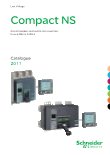
Micrologic control units
Micrologic A "ammeter"
1
long-time threshold and tripping delay
2
overload alarm (LED) at 1.125 Ir
3
short-time pick-up and tripping delay
4
instantaneous pick-up
5
earth-leakage or earth-fault pick-up and tripping delay
6
earth-leakage or earth-fault test button
7
long-time rating plug screw
8
test connector
9
lamp test, reset and battery test
10
indication of tripping cause
11
digital display
12
three-phase bargraph and ammeter
13
navigation buttons
Micrologic A control units protect power circuits.
They also offer measurements, display, communication
and current maximeters. Version 6 provides earth-fault
protection, version 7 provides earth-leakage protection.
Note.
Micrologic A control units come with a transparent lead-seal
cover as standard.
"Ammeter" measurements
Micrologic A control units measure the true (rms) value of currents.
They provide continuous current measurements from 0.2 to 1.2 In and are accurate
to within 1.5 % (including the sensors).
A digital LCD screen continuously displays the most heavily loaded phase (Imax) or
displays the I
1
, I
2
, I
3
, I
N
, I
g
,I∆
n
, stored-current (maximeter) and setting values by
successively pressing the navigation button.
The optional external power supply makes it possible to display currents < 20 % In.
Below 0.1 In, measurements are not significant. Between 0.1and 0.2 In, accuracy
changes linearly from 4 % to 1.5 %.
Communication option
In conjunction with the COM communication option, the control unit transmits the
following:
settings
b
all “ammeter” measurements
b
tripping causes
b
maximeter readings.
b
Protection
Protection thresholds and delays are set using the adjustment dials.
Overload protection
True rms long-time protection.
Thermal memory: thermal image before and after tripping.
Setting accuracy may be enhanced by limiting the setting range using a different
long-time rating plug.
Overload protection can be cancelled using a specific LT rating plug "Off".
Short-circuit protection
Short-time (rms) and instantaneous protection.
Selection of I
2
t type (ON or OFF) for short-time delay.
Earth-fault protection
Residual or source ground return earth fault protection.
Selection of I
2
t type (ON or OFF) for delay.
Residual earth-leakage protection (Vigi).
Operation without an external power supply.
q
Protected against nuisance tripping.
k
DC-component withstand class A up to 10 A.
Neutral protection
On three-pole circuit breakers, neutral protection is not possible.
On four-pole circuit breakers, neutral protection may be set using a three-position
switch: neutral unprotected (4P 3d), neutral protection at 0.5 Ir (4P 3d + N/2), neutral
protection at Ir (4P 4d).
Zone selective interlocking (ZSI)
A ZSI terminal block may be used to interconnect a number of control units to provide
total discrimination for short-time and earth-fault protection, without a delay before
tripping.
Overload alarm
A yellow alarm LED goes on when the current exceeds the long-time trip threshold.
Fault indications
LEDs indicate the type of fault:
overload (long-time protection Ir)
b
short-circuit (short-time Isd or instantaneous li protection)
b
earth fault or earth leakage (Ig or I∆n)
b
internal fault (Ap).
b
Battery power
The fault indication LEDs remain on until the test/reset button is pressed. Under
normal operating conditions, the battery supplying the LEDs has a service life of
approximately 10 years.
Test
Amini test kit or a portable test kit may be connected to the test connector on the
front to check circuit-breaker operation. For Micrologic 6.0 A and 7.0 A control units,
the operation of earth-fault or earth-leakage protection can be checked by pressing
the test button located above the test connector.
DB128033
Functions and characteristics