


 317 / 408

11
11/3
Dimensions
Section 12
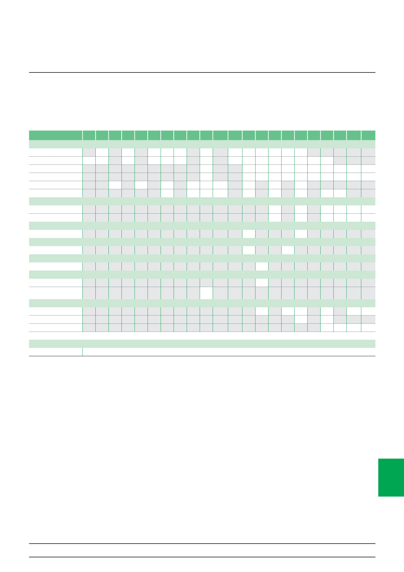
Dissipated power, impedance and
voltage drop (cont.)
Technical advice
Rating (A)
0.5 1 1.6 2 2.5 3 4 6 6.3 10 12.5 13 16 20 25 32 40 50 63 80 100 125
Circuit breakers
iDPN
2.5
1.9
2.1 2.6 2.7
2.7
3.3 3.2 4.7 4.7 4.6 5.8
C60/C60H-DC
2.2 2.3
2.6
2.2 2.4 2.7
1.8
2.5 2.5 3 3.1 3.5 4.3 4.8 6.1
C120
1.3
2.1 2.3 2.5 3.2 3.1 3.2 3 3.2 2 4.1
NG125
1.7
2.4 2.7 2.7 3.8 3.8 4.2 3.8 4.8 4.3 7.9
C60L-MA
2.4
2.5
2.4
3 2 2.5
2.6
3
4.6
NG125L-MA
3
2 2 3.1
2.5
3.2
4
5.5 6
RCCB
ID Type A/AC
1.4
3.6
4.4 7.2 18 28
ID Type B
1.2
2.9
7.2 12 18 28
Contactors
CT/CT+ Power circuit
0.9
1.4
Impulse relays
TL/TL+ Power circuit
0.9
1.4
Push-buttons
PB
0.6
Selector switches
CM
0.8
CMA/CMB/CMC/CMD/
CMV
0.4
Switch-disconnectors
I
0.8
1.3 1.1
1.8
3.4 4.2
I-NA
3.2
3.2
NG125NA
5.5 6 7 9
Indicator lights
V
0.3
Note: When the enclosure's thermal balance, consider the 4P devices load is only on 3 phases
Impedance calculation:
Z = P / I²
Z: impedance in Ohms
P: dissipated power in Watts (table values)
I: rating in Amperes
Voltage drop calculation:
U = P / I
U: voltage drop in Volts
P: dissipated power in Watts (table values)
I: rating in Amperes
The following table indicates the average dissipated power per pole in W for a
current equal to the rating of the device and at the operating voltage.
Multi 9products