


 521 / 576

521
ClimaSys
Thermal management system
Thermal balance
Method of determining the thermal solution
The heat balance, which consists of comparing the power released by the devices
with the power exchanged spontaneously through the wall of the enclosure, allows
us to calculate the internal temperature obtained in the enclosure, with no thermal
accessories, and thus to determine whether it is necessary to install any, bearing
in mind the desired internal and external temperatures.
Below we have presented a simple method for implementing this choice.
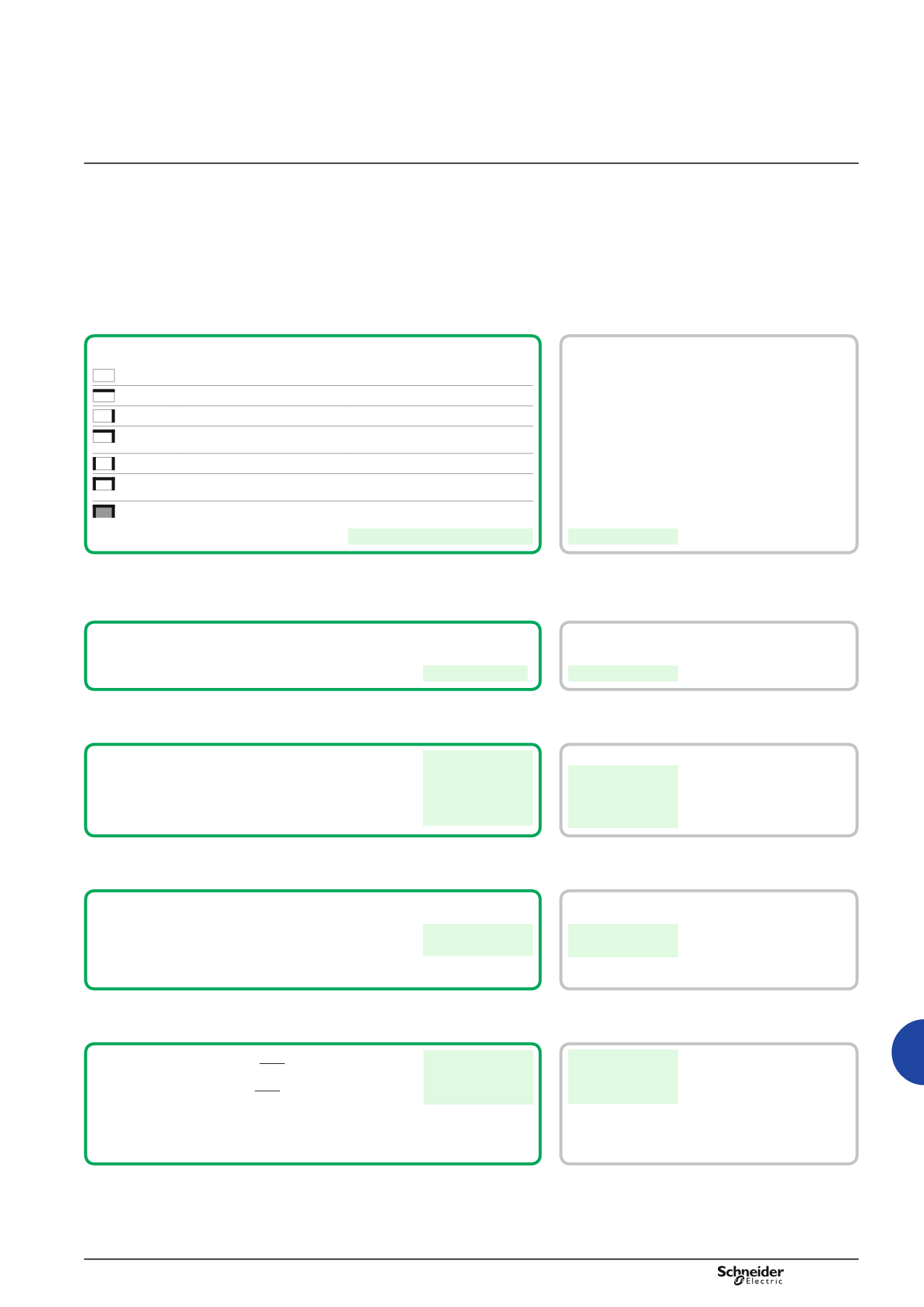
Position of
the enclosure
Location according
to IEC 890 ratio
Formula for calculating S
(m
2
)
Accessible from every side
S = 1.8 x H x (W + D) + 1.4 x W x D
Placed against a wall
S = 1.4 x W x (H + D) x 1.8 x D x H
On the end when suited
S = 1.4 x D x (H + W) + 1.8 x W x H
On the end when suited, placed
against a wall
S = 1.4 x H x (W + D) + 1.4 x W x D
In the middle when suited
S = 1.8 x W x H + 1.4 x W x D + D x H
In the middle when suited, placed
against a wall
S = 1.4 x W x (H + D) + D x H
In the middle when suited, placed
against a wall with the top covered
S = 1.4 x W x H + 0.7 x W x D + D x H
S =
m
2
Example
Spacial reference
NSYSF20840
H = 2000
W = 800
D = 400
Installation method:
Suitable enclosure placed against a wall.
S = 4.43 m
2
1 -
Characteristics of the enclosure
Assume that the switchgear dissipates
800 W.
Calculated as the sum of the power dissipated by each of the installed components.
If these are not known, use the ProClima software and page 526, which shows
the average values.
Pd = 800 W
Pd =
W
2 -
Thermal power dissipated by the operational components
The temperature conditions are as follows:
Maximum ambient temperature.
Te
max
=
°C
Minimum ambient temperature.
Te
min
=
°C
Average relative humidity.
RH =
%
Dew point temperature. Useful to avoid condensation
and to calculate resistance heater power.
Dp =
°C
Te
max
= 35°C
Te
min
= 15°C
RH = 70 %
Dp = 29°C
3 -
Characteristics of the environment air
They are defined by the nature of the components and the
characteristics of the environment air
Maximum internal temperature
Tid
max
=
°C
Minimum internal temperature
Tid
min
=
°C
(maximum value between the dew point temperature
and the minimum operating temperature of the devices)
Tid
max
= 40°C
Tid
min
= 29°C
4 -
Average desired internal temperatures
Max. internal temperature: Tfi
max
= Pd
K x S + Te
max
Tfi
max
=
°C
Min. internal temperature: Tfi
min
= Pd
K x S + Te
min
Tfi
min
=
°C
or K = 5.5 W/m
2
/°C for an enclosure made of painted sheet steel
K = 3.5 W/m
2
/°C for a polyester enclosure
K = 3.7 W/m
2
/°C for a stainless-steel enclosure
K = 12 W/m
2
/°C for an aluminium enclosure
Tfi
max
= 70°C
Tfi
min
= 50°C
5 -
Final temperature inside the enclosure with no thermal system
H = Height - W = Width - D = Depth