


 74 / 210

74
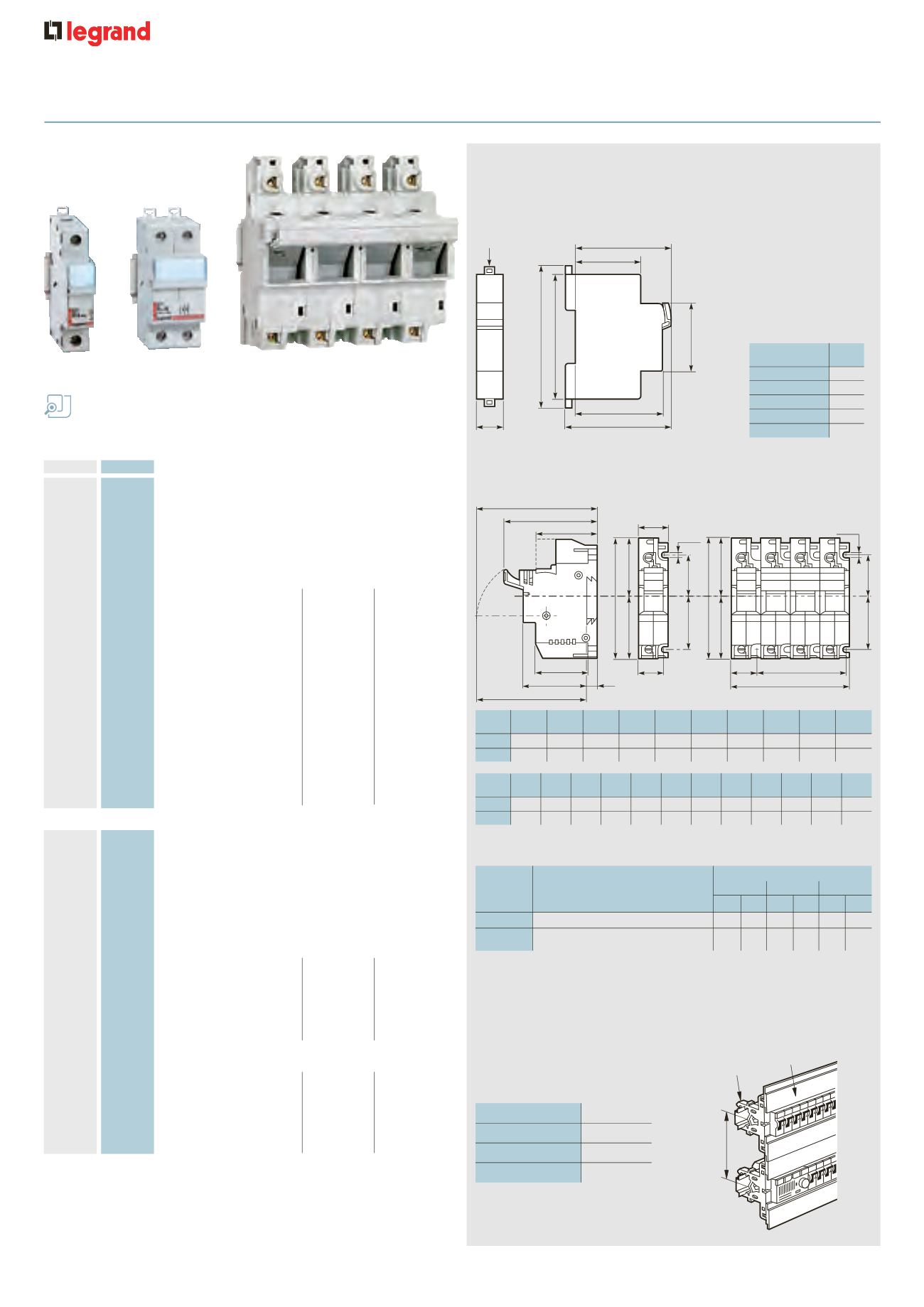
Dimensions
opposite
Accessories
p. 75
modular fuse carriers
for industrial cylindrical cartridge fuses
For HRC cylindrical fuses (see p. 76)
0058 04
0058 28
0216 05
Pack
Cat. Nos.
Modular carriers for HRC type aM and
gG fuses
Conform to IEC 60269-2/2 . 1, isolation to IEC 60947-3
Fix to DIN rail
4
EN 60715
Equipped with label holder
Padlockable using locking accessory Cat. No. 0057 99,
p. 75
Shielded terminals max. capacity 2 x 10 mm
2
Double insulated
O
Class II
Fuse size (mm)
Voltage
±
No. of 17·5 mm
(Volts)
modules
Single pole
10
0058 04 Disconnectable neutral
500
1
10
0058 06 8·5 x 31·5
400
1
10
0058 08 10 x 38
500
1
Single pole + Neutral
10
0058 16 8·5 x 31·5
400
1
10
0058 18 10 x 38
500
1
Double pole
5
0058 28 10 x 38
500
2
Triple pole
3
0058 38 10 x 38
500
3
Triple pole + Neutral
2
0058 48 10 x 38
500
4
SP isolating fuse carriers with protected
terminals
For isolation and protection of electrical circuits
Conform to IEC 60269-2 and BS EN 60269-2
Bureau Veritas approved
Height under front plate : 44 mm
Fix to DIN rail
4
EN 60715 or with screws
SP 51 for HRC type aM and gG fuses 14 x 51
Connection
No. of 17·5 mm
modules
5
0215 01 Single pole
1 x 35 mm
2
1·5
1
0215 03 Double pole
or
3
1
0215 04 Triple pole
2 x 16 mm
2
4·5
1
0215 05 Triple pole +
6
disconnectable neutral
SP 58 for HRC type aM and gG fuses 22 x 58
Connection
No. of 17·5 mm
modules
3
0216 00 Disconnectable neutral
1 x 50 mm
2
2
3
0216 01 Single pole
or
2
1
0216 04 Triple pole
2 x 25 mm
2
6
1
0216 05 Triple pole +
8
disconnectable neutral
n
Choice of equipment
n
Protection index
: IP 2X - IP 2X C - under front plate
n
Equipment derating
Justified under more severe
conditions of use :
• Ambient temperature over 35 °C :
derate fuse by one rating per 10 °C
(UTE C 20-051)
• Side-by-side equipment in
simultaneous function
This coefficient is to be applied on the
nominal rating of the base (IEC 60439-1)
• Continuous operation : it may be necessary
to upgrade the bases by one size
In mm
A
B
B
1
B
2
C
E
G
H
H
J
1 P
multi.
1 P
SP 51
106
54·5
45
35
51·5
55
53
81
84
96
SP 58
140
74
65
45
66
59
53
87
90
111
In mm
A
Single pole
17·7
Single pole + N
17·7
Double pole
35·5
Triple pole
53·4
Triple pole + N
71·2
In mm
J
L
N
U
U
U
V
V
V
V
W
W
multi.
2 P
3 P
4 P
1 P
2 P
3 P
4 P
1 P multi.
SP 51
99
20·7
9
26·5
53 79·5 26·5
53 79·5 106
87
90
SP 58
114
27
9
36
72 108
36
72 108
144 101
109
Maximum cartridge rating
Type
Rated current
400 V
±
500 V
±
690 V
±
gG aM gG aM gG aM
SP 51
50 A
50 50 50 40 25 25
SP 58
100 A
125 125 100 100 50 50
(125 A in 400 V)
2 or 3 devices
0·9 x In
4 or 5 devices
0·8 x In
6, 7, 8 or 9 devices
0·7 x In
≥≤
10 devices
0·6 x In
45
67
Ø 3
44
83
94
60
73
A
J
H
G
A
C
B
B
1
B
2
A
Ø 4 . 4
Ø 4 . 4
V
44
E
W
N
L
C
B
B
2
B
1
L
U
V
n
Modular fuse carriers
Conform to IEC 60269-2/2·1, isolation to IEC 60947-3
Icc : 20 kA with 8·5 x 31·5 fuse
100 kA with 10 x 38 fuse
Operating temperature : –5 °C to +40 °C
Mechanical resistance : IPXX 3
127 to 136 mm
Insulated
support
0016 90
Protective
terminal shield
0016 91
n
Modular protective
terminal shield mounting
(see p. 75)
n
SP 51 and SP 58 fuse carriers
Conform to IEC 60269-2 and BS EN 60269-2
Bureau Veritas approved