


 60 / 210

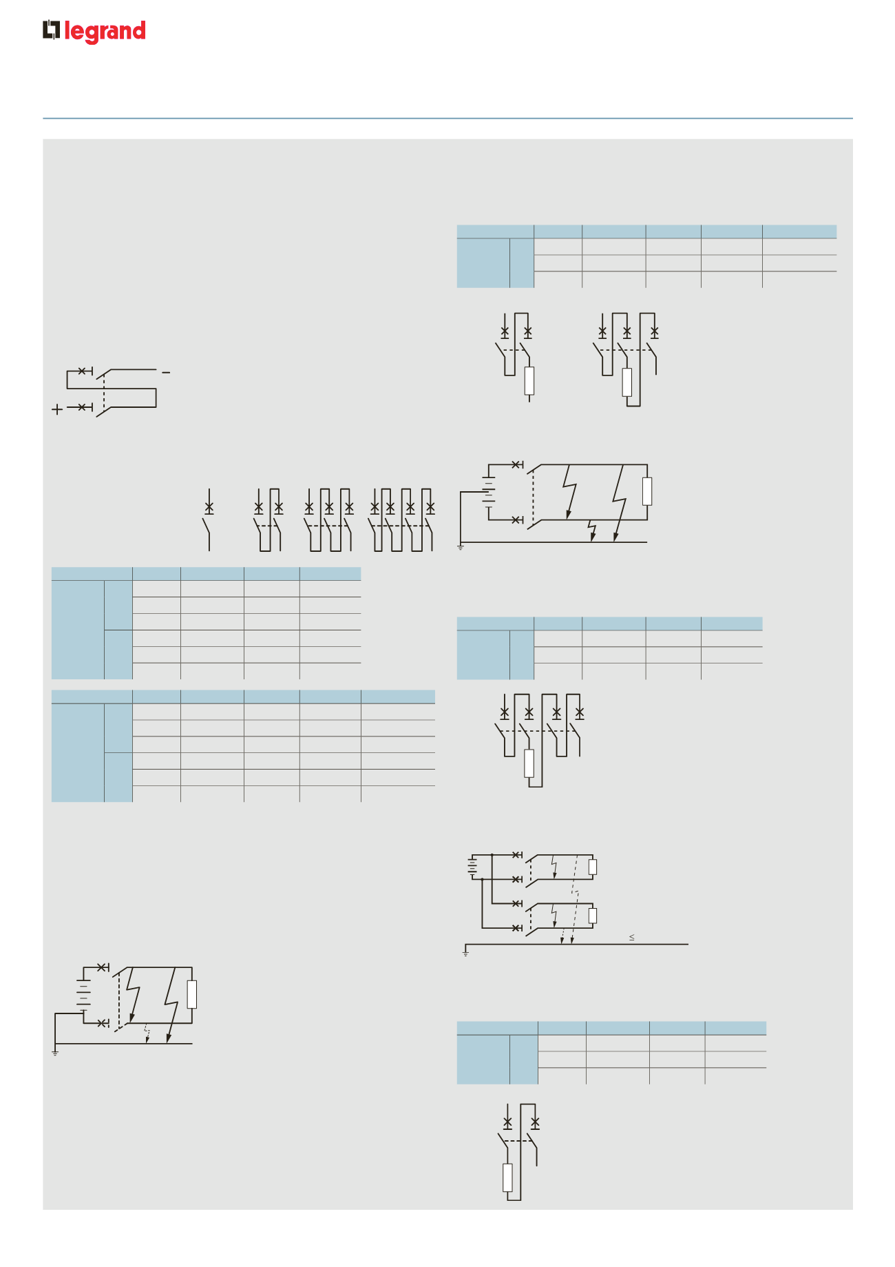
60
protection of DC circuits
DX
3
10000
voltage single pole
2P
3P
4P
Acc. to
IEC 60947-2
Icu
≤
48 V
10 kA
10 kA
110 V
10 kA
10 kA
230 V
15 kA
DX
3
6000
voltage single pole
2P
3P
Acc. to
IEC 60947-2
Icu
≤
48 V
6 kA
6 kA
110 V
6 kA
6 kA
230 V
DX
3
6000
voltage single pole
2P
3P
Acc. to
IEC 60947-2
Icu
≤
48 V
6 kA
6 kA
110 V
6 kA
6 kA
230 V
Example : circuit earthed via the negative polarity / U = 110 V
=
/ Isc =
10 kA / In = 32 A
Protect the positive polarity using an MCB capable of breaking 10 kA
at 110 V (DX
3
10000 2P 32 A with 2 poles on the positive polarity)
For isolation, use a DX
3
10000 3P 32 A with 2 poles on the positive
polarity and one pole on the negative polarity
1 : MCB (U/2-Isc max.)
1
1
U/2
U/2
U-Isc max.
U/2-Isc max.
U/2-Isc max.
+
-
U-Isc max.
U-Isc max.
1
st
earth fault : I = O
2
nd
earth fault :
U and I Isc max.
U
+
-
1 : MCB (U-Isc max.)
1
1
•
Network earthed via a middle point:
Place on each polarity the number of poles necessary for max. Isc
breaking at half voltage
Example : circuit earthed via a middle point / U = 230 V
=
/ Isxc = 6 kA
/ In = 10 A
Protect each polarity using an MCB capable of breaking 6 kA at half
voltage, i.e. 115 V (DX
3
6000 4P 10 A with 2 poles on each polarity)
•
Isolated earth supply:
Distribute the poles necessary for breaking over the 2 polarities to
provide protection in the event of a double earth fault (particularly if
there are a number of circuits in parallel)
Example : isolated earth circuit / U = 48 V
=
/ Isc = 4 . 5 kA / In = 40 A
Protect the installation with an MCB capable of breaking 4 . 5 kA at
48 V and protect each polarity (DX
3
6000 MCB 2P 40 A with one pole
on each polarity)
Example : for a 110 V voltage,
use a 2 pole MCB and connect
the 2 poles in series
4 - Breaking capacity
For other voltages, the breaking capacities are as follows:
4000 A for a single pole MCB at max. voltage (80 V
=
per pole)
+
-
+
-
+
-
+
-
1 : Only if isolation required
MCB
(U-Isc max.)
U
U-Isc max
U=0
1
+
-
5 - Distribution of breaking poles
Place all the poles necessary for breaking on the other polarity
If isolation is required, an additional pole must be added on the
earthed polarity
•
Supply with one polarity earthed:
To choose the MCB and determine the pole distribution necessary
for breaking on each of the polarities, it is necessary to know how the
installation is earthed
DX
3
6000
voltage single pole
2P
3P
Acc. to
IEC 60947-2
Icu
≤
48 V
6 kA
6 kA
110 V
6 kA
6 kA
230 V
Ics
1
≤
48 V
100 % 100 %
110 V
100 % 100 %
230 V
DX
3
10000
voltage single pole
2P
3P
4P
Acc. to
IEC 60947-2
Icu
≤
48 V
10 kA
10 kA
110 V
10 kA
10 kA
230 V
15 kA
Ics
1
≤
48 V
100 % 100 %
110 V
100 % 100 %
230 V
100 %
1 : As a % of Icu
+
-
DX 10 A
4P
DX
3
6000
10 A 4P
DX 40 A
2P
+
-
DX
3
6 00
40 A 2P
DX-H 32 A
2P
DX-H 32 A
3P
If isolation required
+
+
-
-
3
10000
32 A 2P
3
10000
32 A 3P
n
Protection of DC circuits
DX
3
6000 and DX
3
10000 MCBs (1P/2P/3P/4P - In
≤
63 A) designed for
use in 230/400 V
±
supplies, can also be used in DC circuits
In this case, the following deratings and precautions must be taken into
account
Max. magnetic tripping threshold : multiplied by 1. 4
Example : For a C curve MCB for which the AC tripping threshold is
between 5 and 10 In, the DC tripping threshold will be between
7 and 14 In
Max. operating voltage : 80 V per pole (60 V for single pole + N MCBs)
For voltages higher than this value, several poles must be wired in series
The time/current thermal tripping curve is the same as for AC
1 - Protection against short-circuits
2 - Protection against overloads
3 - Operating voltage