


 58 / 210

58
Dimensions
p. 65
Technical information
p. 59-60
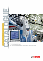
auxiliaries for MCBs DX
3
4062 58
4062 66
Pack
Cat. Nos.
Auxiliaries for MCBs
Clip on the left hand side of the MCB (maximum 3)
Allow insertion of the supply busbar at the top
Auxiliaries common to DX
3
MCBs, RCDs and RCBOs
Signalling auxiliaries
Number of modules
1
4062 58 Auxiliary changeover switch,
6 A - 250 V
±
Indicates the position of the
contacts
0 . 5
1
4062 60 Fault signalling changeover
switch, 6 A - 250 V
±
Indicates tripping of the MCB
at a fault
0 . 5
1
4062 62 Auxiliary changeover switch,
6 A - 250 V which can be modified
to a fault signalling switch
0 . 5
1
4062 66 Auxiliary changeover switch,
6 A - 250 V + fault signalling
switch, can be modified to 2
auxiliary changeover switches
1
Pack
Cat. Nos.
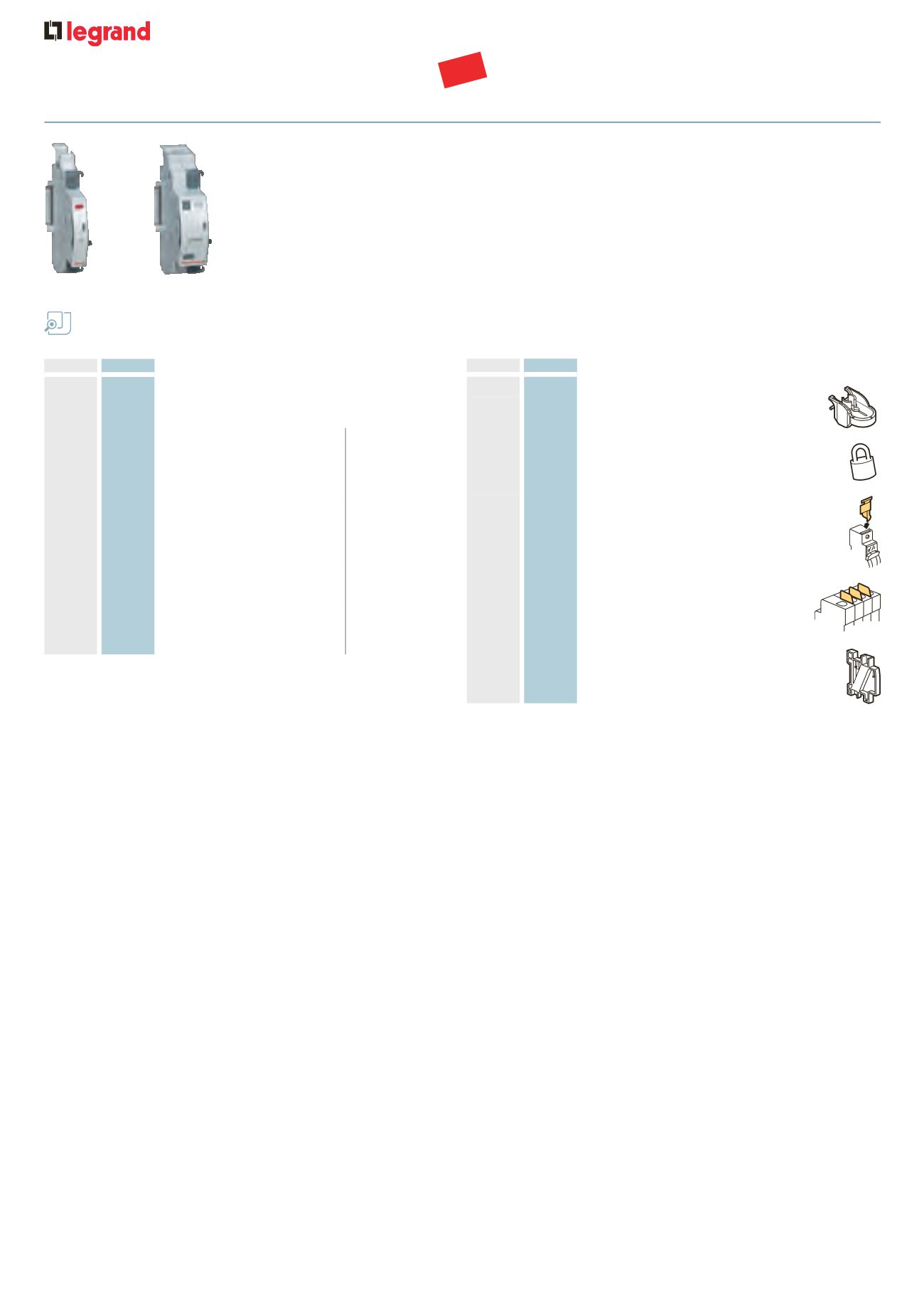
Accessories
Padlocking
2
4063 03 Support for one
Ø
5 mm padlock for
DX
3
MCBs and RCDs or isolating switches
3
4063 13
Ø
5 mm shackle type padlock
Sealable screw cover - 4 separable poles
2
4063 04 For DX
3
MCBs, 1 module per pole
Insulating shields
For DX
3
MCBs, 1 module per pole
1
4063 05 Pole insulating shield (set of 6)
Spacing element
10
4063 07 For heat reduction – 0 . 5 module
NEW
a093505a