


 59 / 210

59
technical information
n
Breaking capacity in IT neutral earthing system
MCB single pole breaking capacity at 400 V
according to IEC 60947-2
DX
3
10000
16 kA
1P/2P/3P/4P
4 kA
n
Breaking capacity in the event of short-circuit to earth
and insulation voltage
Icn 1 : Breaking capacity on 1 pole for multipole MCBs in the event of
short-circuit to earth
Ui : Rated insulation voltage
1P/2P/3P/4P
230/400 V
A
MCBs
DX
3
10000
16 kA
Icn1
16000 A
Ui
500 V
n
Terminal connection cross-sections (mm
2
)
Copper cable
Rigid Flexible
DX
3
6000 10 kA
35
25
DX
3
10000 16 kA
Auxiliaries
2 . 5
2 . 5
n
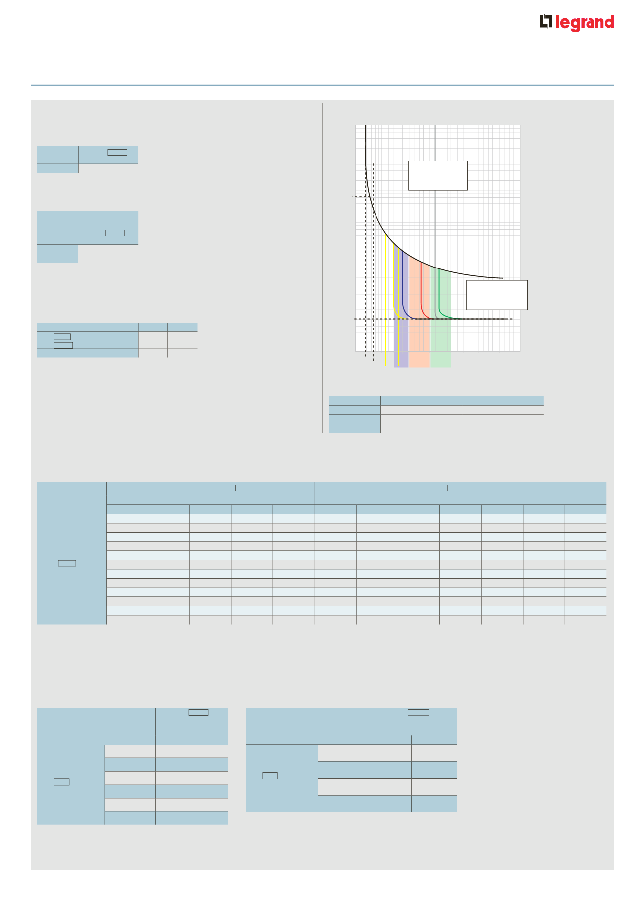
MCB tripping curves
n
MCB selectivity table
MCBs/MCBs (in A)
n
Back up between MCBs (in kA)
In 3 phase networks + N 400/415 V
according to IEC 60947-2
In 3 phase networks + N 230/240 V
according to IEC 60947-2
1
1.3 1.45
3 4 5
10
20 30 50
100 200
x In (rating)
Thermal tripping for an ambient temperature 30 °C
In = nominal current (rating) of MCB
Magnetic
(high overcurrent :
fast tripping)
D
C
B
D
C
B
Thermal
(low overcurrent :
slow tripping)
2
0.01 s
1 h
t (time)
Curves
Magnetic threshold settings
B
3 to 5 In
C
5 to 10 In
D
10 to 14 In
(10 to 20 acc. to the stds)
n
Technical characteristics of auxiliaries
Max. connection cross-section : 2 . 5 mm
2
Operating temperature : –25°C to +70°C
Signalling auxiliaries
Umin. : 24 V
±
/
=
and Imin. : 5 mA
Upstream
MCB
DX
3
10000 - 16 kA
DX
3
10000 - 16 kA
B curve
C curve
Downstream MCB
In (A)
32
40
50
63
32
40
50
63
80
100
125
DX
3
10000 - 16 kA
B & C curve
≤
6
128
160
200
252
240
300
375
472
4000
T
T
10
128
160
200
252
240
300
375
472
3000
5000
T
16
128
160
200
252
240
300
375
472
2000
3600
5500
20
160
200
252
240
300
375
472
1600
3000
4000
25
200
252
240
300
375
472
1300
2400
3300
32
252
300
375
472
1000
1800
2700
40
375
472
800
1600
2400
50
472
800
900
1700
63
650
900
1200
80
600
750
100
750
125
T : total selectivity, up to downstream circuit breaker breaking capacity according to IEC 60947-2
The magnetic threshold and the nominal rating of the downstream MCB must always be inferior to the ones of the upstream MCB
MCBs upstream DX
3
10000
16 kA
B, C and D curves
MCBs downstream
10 to 125 A
DX
3
6000 - 10 kA
B, C and D curves
≤
20 A
16 kA
25 A
16 kA
32 A
16 kA
40 A
16 kA
50 A
16 kA
63 A
-
MCBs upstream
DX
3
10000
16 kA
B, C and D curves
MCBs downstream
≤
32 A 40 to 125 A
DX
3
6000 - 10 kA
B, C and D curves
≤
20 A
32 kA
25 kA
25 to 40 A
-
25 kA
50 A
-
25 kA
63 A
-
25 kA