


 45 / 210

45
n
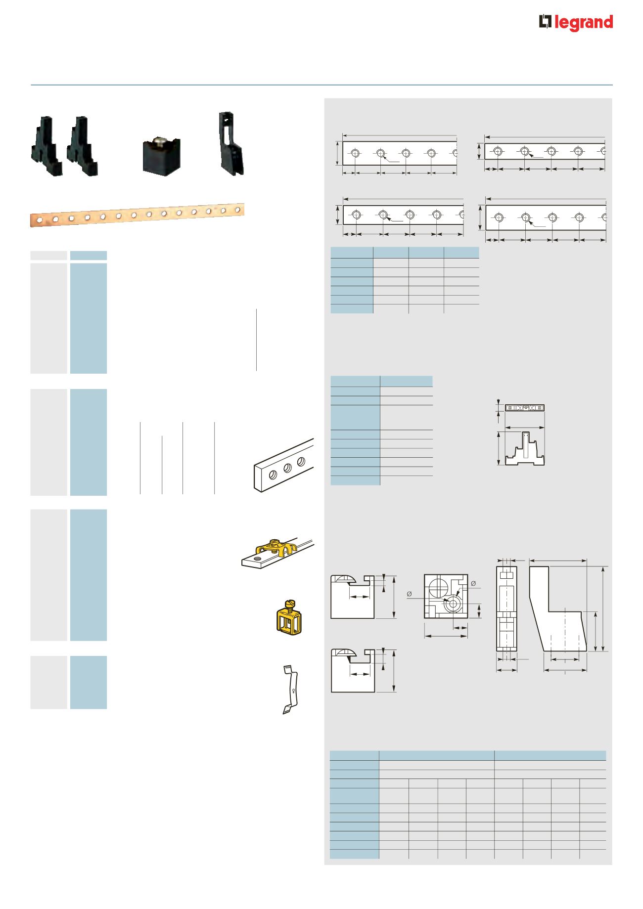
Copper connector bars with threaded holes
Cat. Nos. 0373 88/89
Cat. Nos. 0374 33/34
n
Insulated supports
four pole
Insulation voltage according to EN 60947-1/IEC 60664-1 :
Cat. No. 0373 96 : 690 V - Impulse voltage (surge) (Uimp) : 8 kV
Degree of pollution (conductive dust) : 3
Distance between supports (mm)
990
18
18
18
18
9
12
M5
037438c
990
18
18
18
18
9
25
M6
c037438
990
18
18
18
18
9
15/18
M6
c037433
1 750
50
50
50
50
9
32
M6
c037419
Cat. No. 0374 37
Cat. No. 0373 98
6 . 2
53
25
6 . 2
17 . 5
35
75
42
= =
= =
c037437
12 . 4
25 . 5
2
12 . 4
25 . 5
4
4 . 5
9
25 . 5
8 . 7
8 . 7
c037398
12 . 4
25 . 5
2
12 . 4
25 . 5
4
4 . 5
9
25 . 5
8 . 7
8 . 7
c037398
12 . 4
25 . 5
2
12 . 4
25 . 5
4
4 . 5
9
25 . 5
8 . 7
8 . 7
c037398
Cat. Nos.
Size
Ithe (A)
Ic (A)
0373 88
12 x 2
110
80
0373 89
12 x 4
160
125
0374 33
15 x 4
200
160
0374 34
18 x 4
245
200
0374 38
25 x 4
280
250
0374 19
32 x 5
450
400
Current ratings according to
EN 60947-1 :
• Ith : bars in free air
• Ithe : bars enclosed with
ventilation
• Ic : bars totally enclosed in
a weatherproof enclosure
Cat. No. 0374 38
Cat. No. 0374 19
Cat. Nos.
0373 96
Bar size
12 x 4 (12 x 2)
In (A)
125 (80)
Peak withstand
current (kA)
10
400 (200)
15
300 (150)
20
200 (125)
25
150 (100)
30
–
35
–
40
–
Cat. Nos.
0373 98
0374 37
Bar size
12 x 2/12 x 4
15 x 4/18 x 4/25 x 4
In (A)
80/125
160/200/245
E (mm)
50
75
100
125
50
75
100
125
Peak withstand
current (kA)
10
400
600
800
–
350
600
750
–
15
300
450
600
800
250
400
500
700
20
250
350
450
600
150
225
300
375
25
200
250
300
400
125
150
200
250
30
–
–
–
–
100
125
150
175
35
–
–
–
–
–
100
125
150
n
Insulated supports single pole
Insulation voltage according to EN 60947-1/IEC 60664-1 : 500 V
Impulse voltage (surge) (Uimp) : 8 kV
Degree of pollution (conductive dust) : 3
Front view for
12 x 2 mm bar
Front view for
12 x 4 mm bar
View from
above
Max. space between 2 supports :
bar size 12 x 2 : 20 cm, 12 x 4 : 25 cm
The distance between supports can be determined using the chart
Select the peak withstand current (kA rating) and the distance between
bars - dimension E (mm) after choosing your bar and support
Distance between supports (mm)
037365
037389
Copper connector bars
With threaded holes
Threaded
Max.
Size
holes
thermal
Length
(mm)
Ø mm Pitch rating (A)
(mm)
10
0373 88 12 x 2 M5 18 110 990
10
0373 89 12 x 4 M5 18 160 990
10
0374 33 15 x 4 M6 18 200 990
10
0374 34 18 x 4 M6 18 245
990
10
0374 38 25 x 4 M6 18 280
990
4
0374 19 32 x 5 M6 25 450 1 750
Connectors
Clamp type – For bars with
threaded holes
12 x 4 (mm)
For one or two conductors
100
0373 65 1·5 to 10 mm
2
(supplied with
Ø 5 mm screw)
Cage type – For bare 12 x 4 mm bars
Capacity
100
0373 60 1·5 to 4 mm
2
10
0373 61 6 to 16 mm
2
10
0373 62 10 to 35 mm
2
(supplied with
hexagonal 5 mm M6 screw)
Clips
For mounting on rail EN 60715
4
and
3
15 mm depth
10
0044 16 10 mm width
With threaded Ø 4 mm hole
006187-5342o.eps
0373 96
0374 37
0373 98
0374 33
Pack
Cat. Nos.
Insulated supports (maximum 280 A)
For assembling distribution blocks of varying
lengths using bars and connectors below
Supplied with insulated screws for mounting
optional protective cover (except Cat. No. 0373 98)
Set of 2 insulated 4 pole supports
Mounting type
5
0373 96 For bars 12 x 2 or 12 x 4 mm
DIN rail 0044 16
supplied or M4
screws not supplied
Single pole supports
10
0373 98 For bars 12 x 2 or 12 x 4 mm
by M4 screws
10
0374 37 For bars 15 x 4, 18 x 4 or 25 x 4 mm
supplied
n037360
Cat. No. 0373 96
70
14
83
distribution blocks
s
elf assembly