
99
All dimensions (mm) are nominal
n
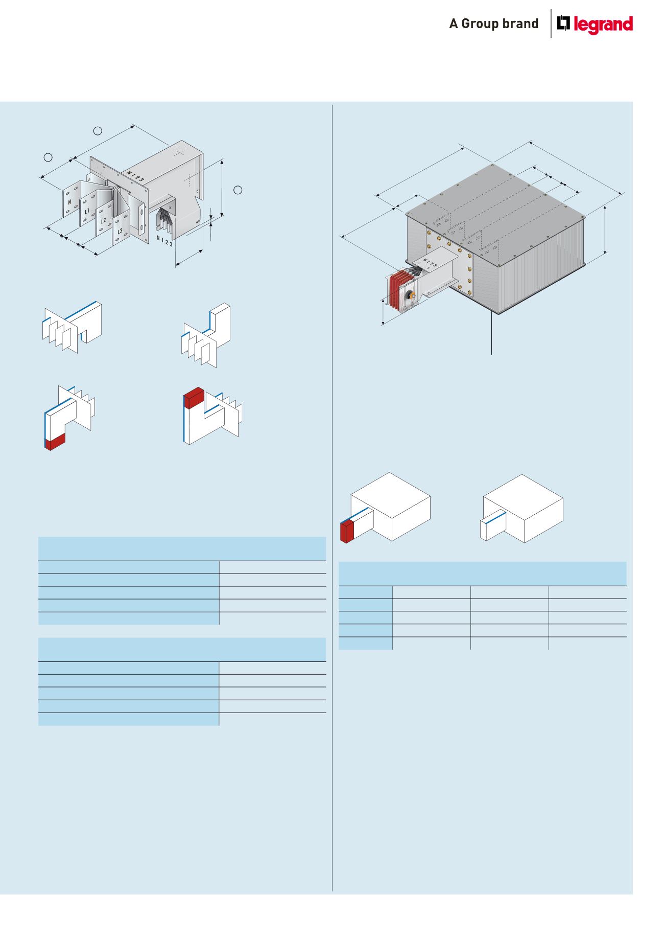
Connection interfaces + vertical elbows
minimum and maximum dimensions of single bar
Aluminium
630 A to 2000 A
Copper
800 A to 2500 A
(A) min. / max. (mm)
150 / 1 299
(B) min. / max. (mm)
300 / 1299
(U) min. / max. (mm)
150 / 400
minimum and maximum dimensions of double bar
Aluminium
2500 A to 4000 A
Copper
3 200 A to 5000 A
(A) min. / max. (mm)
300 / 1 449
(B) min. / max. (mm)
450 / 1449
(U) min. / max. (mm)
150 / 400
H
(1)
(2)
200
300
450
U
B
300
450
A
10
100
100
100
A
Type 3 – male
U
B
Type 1 – female
A
U
B
Type 2 – female
A
U
B
Type 4 – male
A
U
B
Dimension H changes with the rating and is specified on p. 112-117
The dimensions refer to standard tees (bold = double bar)
See p. 100 for dimensions of cover plate (1) and bars (2)
Connection interfaces + vertical elbows – bespoke dimensions
Please specify required dimensions when ordering
n
Feed units
End feed unit
Dimensions of the box
Aluminium 630 A to 1250 A 1600 A to 2000 A 2 500 A to 4000 A
Copper
800 A to 1250 A 1600 A to 2500 A 3 200 A to 5000 A
(A) (mm)
320
320
600
(B) (mm)
600
600
600
(C) (mm)
610
810
810
Dimension H changes with the rating and is specified on p. 112-117
Rear cable input
Aluminium gland plate(s) for cable entry
170mm x 410mm
Single bar : 1 plate
Double bar : 2 plates
100
H
C
300
100
200
100
B
A
For dimensions
of holes for
connections,
see p. 100
Type 2 – female
Type 1 – male


