


 122 / 132

122
DPX
®
160
ME160N/B/N/H - 3P-4P - 400V a.c.
ME250B/B/N/H - 3P-4P - 400V a.c.
25
40
63
100
160
ME160B
ME160H
ME160N
Icc (A)
10
1
10
2
10
3
10
4
10
5
10
9
10
8
10
7
10
6
10
5
10
4
10
3
I
2
t (A
2
s)
25
40
63
100
160
ME250B
ME250H
ME250N
250
Icc (A)
10
1
10
2
10
3
10
4
10
5
10
9
10
8
10
7
10
6
10
5
10
4
10
3
I
2
t (A
2
s)
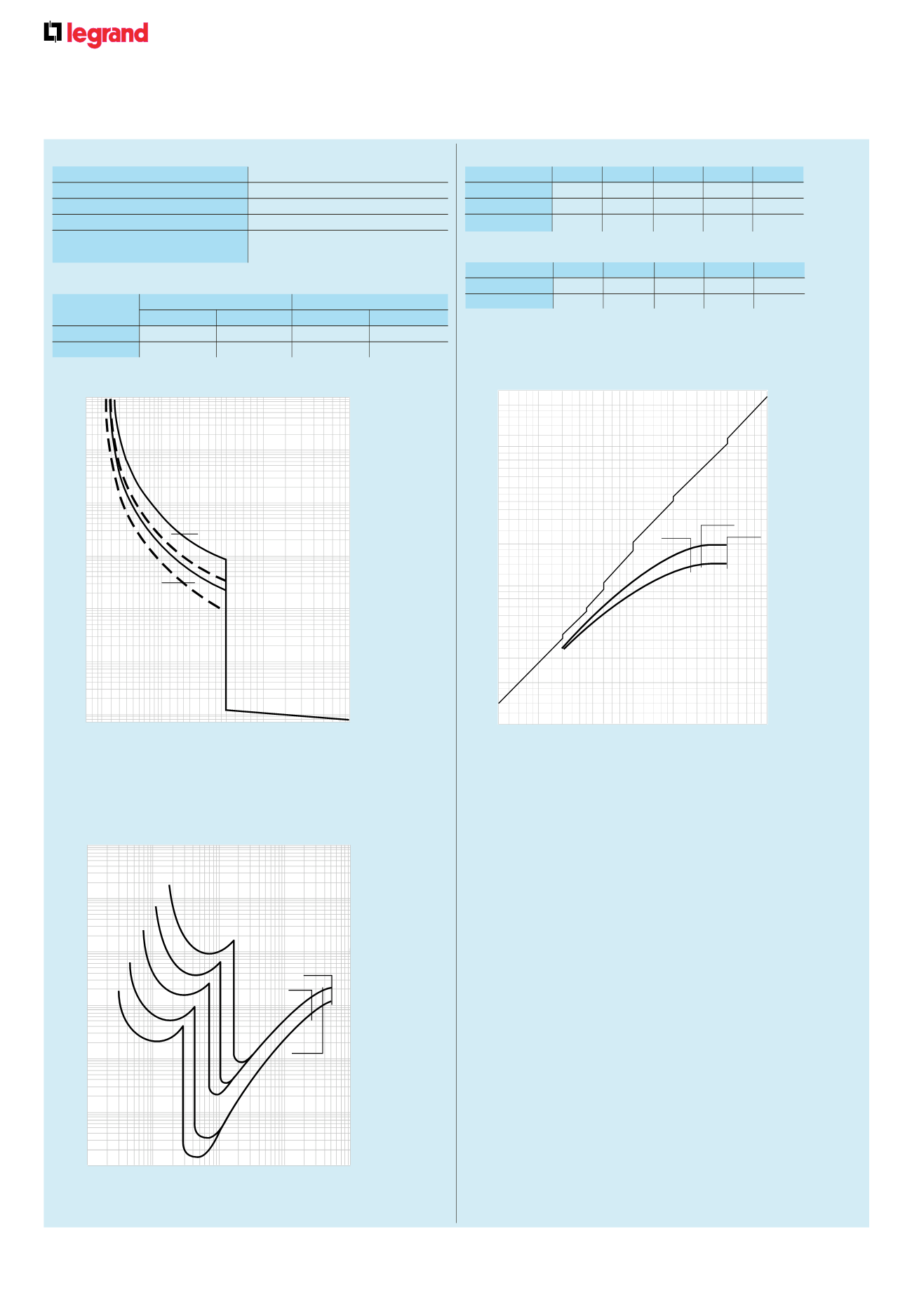
n
Current limitation curves
ME160B/N/H - ME250B/N/H 3P-4P - 400V a.c.
MA/MH160 - MA/MH/ML250 3P-4P - 400V a.c.
1
2
10000
1000
100
10
1
0·01
0·1
t (s)
1
3 2
4 5
10
20 30 50 100
I/Ir
1
3 2
4 5
10
20 30 50 100
I/Ir
1
2
10000
1000
100
10
1
0,01
0,1
t (s)
10
5
2
3
4
100
50
20
30
40
200
1
IP (kA)
1
2 3 4 5
20
10
30 40 50
100
Icc (kA)
0,9
0,8
0,7
0,5
0,3
0,25
0,2
100 -125A
MA125
ME125B
40-63A
16-25A
ME125N
MA/ME125 - 3P-4P - 400V a.c.
ME160B/N/H - 3P-4P - 400V a.c.
ME250B/N/H
10
5
2
3
4
100
50
20
30
40
200
1
IP (kA)
1
2 3 4 5
20
10
30 40 50
100
Icc (kA)
0·9
0·8
0·7
0·5
0·3
0·25
0·2
160A
25A
ME160N
ME160H
ME160B
0,9
10
5
2
3
4
100
50
20
30
40
200
1
IP (kA)
1
2
n
Thermal stress limitation curves
at ambient
θ
= 40 °C
I = actual current
Ir = max. adjustment current of thermal release
➀
= thermal release zone when cold
➁
= thermal release zone when hot (in steady state)
Icc = prospective short-circuit symmetrical current
(rms values in A)
I
2
t = limited thermal stress (in A
2
s)
Icc = prospective short-circuit symmetrical current
(rms values in kA)
IP = maximum peak value (kA)
➀
= current, max. peak, short-circuit rms
➁
= current, unlimited peak (max.), corresponding to power factors shown above (0·15 to 0·9)
Fixed magnetic threshold (Im) (A)
(1)
for DPX 160
In (A)
25
40
63
100
160
Phase
250
400
630
1 000
1 600
N
–
–
–
630
1 000
n
Tripping curves
Nominal breaking capacity (kA) (BS EN 60947-2)
DPX 160 25 kA DPX 160 50 kA
Ue
Icu (kA) Ics (%Icu)
Icu (kA) Ics (%Icu)
400 V
±
25 100
50 50
230 V
±
40 1 0
65 50
n
Electrical characteristics
Nominal current (In) at 40 °C (A) for DPX 160
In (A)
25
40
63
100
160
Phase
25
40
63
100
160
N
25
40
63
100
160
N/2
–
–
–
63
100
Maximum nominal operating function
500 V
±
- 250 V
=
Nominal frequency
50/60 Hz
Category of use
A
Thermal adjustment
0·64 to 1 In
Maximum permitted cross sections
stranded cables : 95 mm
2
for integral cage terminals
flexible cables : 70 mm
2
copper bar (width) : 18 mm
(1) Trip current for 50/60 Hz
For direct current, multiply by 1·5