
124
DPX
®
400
Nominal breaking capacity (kA) (BS EN 60947-2)
DPX 400
Ue
Icu (kA) Ics (%Icu)
400 V
±
36 100
230 V
±
60 100
Nominal current (In) for DPX 400
Phase
320
400
N
320
400
N/2
250
250
n
Electrical characteristics
Maximum nominal operating function
690 V
±
Nominal frequency
50/60 Hz
Category of use
A
Thermal adjustment
0·8 to 1 In
Magnetic release
0·5 to 10 In
Maximum permitted cross sections :
stranded cables : 300 mm
2
(or 2 x 240 mm
2
)
-
via optional cage terminals
flexible cables : 240 mm
2
(or 2 x 185 mm
2
)
- via optional high capacity screw terminals
copper bar (width) : 32 mm (M10
n
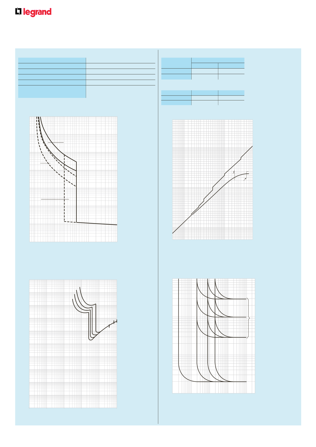
Tripping curves
at ambient
θ
= 40 °C
I = actual current
Ir = max. adjustment current of thermal release
➀
= thermal release zone when cold
➁
= thermal release zone when hot (in steady state)
➂
= magnetic release zone
n
Thermal stress limitation curves
Icc = prospective short-circuit symmetrical current
(rms values in A)
I
2
t = limited thermal stress (in A
2
s)
n
Current limitation curves
Icc = prospective short-circuit symmetrical current
(rms values in kA)
I
2
t = limited thermal stress (in A
2
s)
10000
1000
100
10
1
0 . 01
0 . 001
0 . 1
t(s)
1
3 2
4 5
10 20 30 50 100
I/In
1
2
025521-15142u.eps
3
025253-34914u.eps
0 . 9
0 . 8
0 . 7
0 . 5
0 . 3
0 . 25
0 . 2
Icc(kA)
10
0
10
10
1
10
2
10
3
2 3 4 5
2 3 4 5
10
1
10
2
2
3
4
5
2
3
4
5
2
3
4
5
IP (kA)
DPX 630 36 kA
DPX-H 630 70 kA
320 - 630 A
0
10
0
10
0
10
1
10
2
10
3
10
4
10
5
10
6
10
7
10
8
10
9
10
10
I t (A s)
2
2
10
1
10
2
10
3
10
4
10
5
Isc (A)
250
320
400
630
DPX-H
DPX
25606-26213u.eps
026002-34795u.eps
In 3 A
In 1 A
In 0 . 3 A
b
a
0 . 01
0 . 01
0 . 02
0 . 05
0 . 1
0 . 2
0 . 5
1
2
t (s)
5
10
0 . 05 0 . 1 0 . 5 1
5 10 50 100 300
I (A)
In 0 . 03 A
ID(A) = earth leakage current
IDn = nominal earth leakage current
a = instantaneous tripping point
b = 3 possible delay settings (0·3, 1 and 3 seconds)
n
Differential tripping curves


