


 312 / 319

5
showing the protective
device’s I
2
t characteristics (see
figure 1).
Provided that the fault levels
are within the minimum and
maximum values specified in
figure 1, the flexible cord will
be protected against thermal
damage and comply with the
Wiring Regulations.
Q
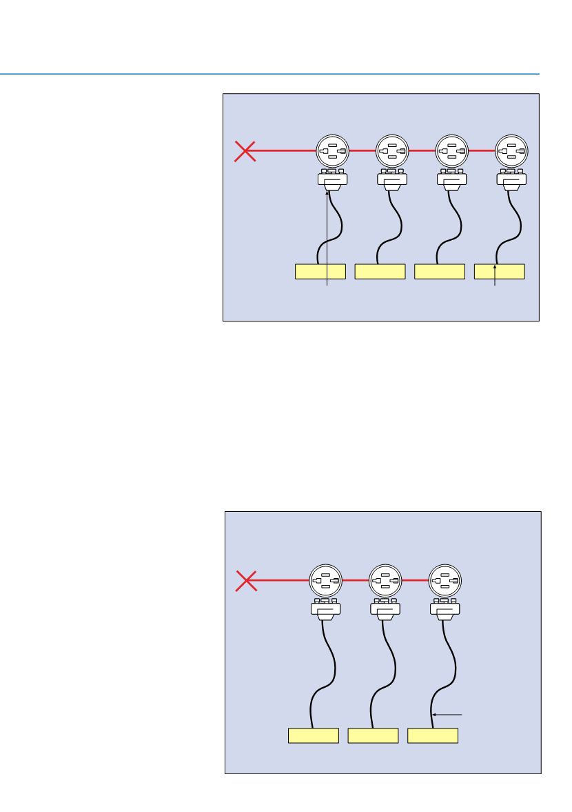
Where are the minimum
and maximum fault currents
likely to occur?
The minimum fault current will
probably be determined by the
earth loop impedance at the
end of the flexible cord at the
furthest LSC. The maximum
fault current will probably be
between live conductors at
the LSC closest to the origin
of the circuit (see figure 2).
Q
Are these calculations
always necessary?
Where an overcurrent
protective device provides
overload protection and
has
a breaking capacity not
less
than the prospective
fault
current at its point of
installation, it can be assumed
that the conductors on
the load side of the device
are protected against fault
current.
This assumption applies when
the neutral and protective
conductors are of equal
cross sectional area to
the line conductor and are
manufactured of the same
material. Such an assumption
must be checked for
conductors in parallel and for
non-current limiting types of
circuit breaker. In this instance
no further calculations are
necessary for overload or
fault current protection (See
figure 3).
Q
Is it possible to purchase
flexible cord with 1.0mm
2
conductors prewired to an
LSC plug?
Yes, Klik, for example, offers
this as standard.
Q
Are there any other key
factors affecting the selection
of flexible cord?
The flexible cord length is
influenced by voltage drop,
protection against electric
shock, the effects of fault
current and the selection and
erection of the wiring system.
Figure 2: The maximum fault current usually lies between the
conductors at the LSC closest to the origin of the circuit
6 A "Klik"
2.5 mm
2
conductor
Hager 16
A type C
circuit
break
er
Flexible
cord with
0.75 mm
2
conductor
Position of maximum fault current
of 1900 A ie minimum impedance
Position of minimum fault current
of 120 A ie maximum impedance
Figure 3: An example of when further calculation is not required
for overload or fault current protection of the flexible cord
Hager 10 A
current limiting
circuit breaker
complying with
BS EN 60898
Breaking capacity of
the circuit breaker
is greater than
the prospective
fault current
at point of
installation
2.5 mm
2
conductor
6 A “klik”
Flexible cord
1.0mm
2
l
z
(current
carrying capacity)
has been
calculated to be
greater than or
equal to 10A.
Line, neutral and
cpc are of equal
cross-sectional
area and are of
the same
material.