


 311 / 319

4
Overload protection is not
required for the flexible cord
from the luminaire supporting
coupler plug to the luminaire.
However, we need to
ensure that the conductors
concerned are large enough
to carry any fault currents
without damage until the
overcurrent device operates.
This section describes how
to make the necessary
calculation.
Q
How would you define
fault current?
A fault current is an
overcurrent caused by either
a short circuit (between
live
conductors) or an earth fault
(between a live conductor and
an exposed conductive part or
protective conductor).
Q
What do the Wiring
Regulations specify to protect
the flexible cord against fault
current?
If overload protection is not
required then a calculation
must be made. Regulation
434.5.2 provides an equation
for calculating the maximum
duration of the fault current,
but it is not immediately
apparent how to apply it. A
simple transposition, however,
gives us the equation.
I
2
t ≤ k
2
S
2
•
where I
2
t is proportional to
the thermal energy let through
the protective device;
•
k
2
S
2
indicates the thermal
capacity of the conductor.
If the conductor is not to be
damaged I
2
t must not exceed
k
2
S
2
;
•
t = the maximum fault
current duration in seconds
(disconnection time);
•
k = a factor taking account
of the resistivity, temperature
coefficient and heat capacity
of the conductor material,
and the initial and final
temperatures, derived from
BS 7671;
•
S = the nominal cross
sectional area of the
conductor in mm
2
;
•
I = the value of fault current
an amperes, expressed for ac
as the rms value, due account
being taken of the current
limiting effect of the circuit
impedances.
Note for very short duration
(less than 0.1 secs) and for
current limiting devices, I
2
t
must be designated by the
manufacturer’s data.
Q
How do I apply this
formula?
The simplest way of assessing
the degree of thermal
protection provided by an
overcurrent device is by
using the manufacturer’s I
2
t
characteristics. Calculate k
2
S
2
and
superimpose this value as a
horizontal line on the graph
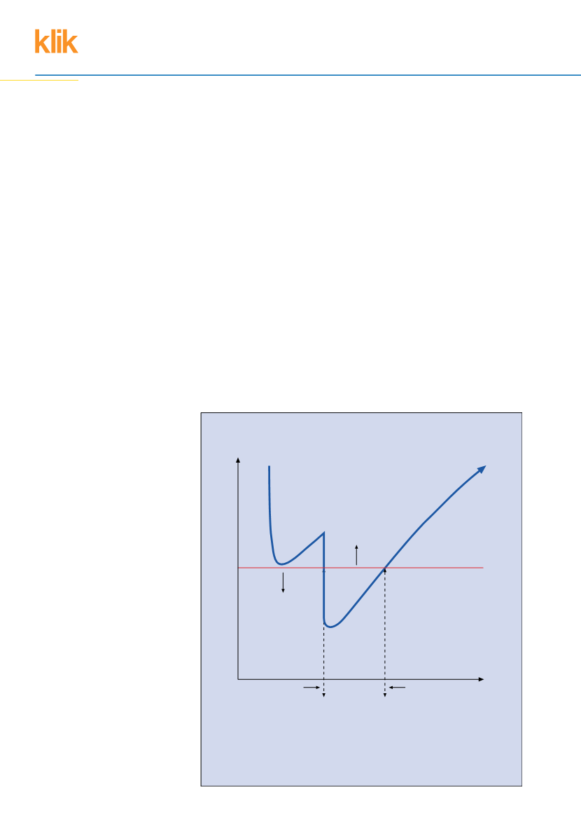
Fault current protection
Figure 1: Assessing protection using the manufacturer's data
I
2
t(A
2
s)
5625
PFC(A)
0091
021
I
2
t characteristic Hager 16 A
type C circuit breaker to
BS EN 60898 (MCB)
Area above red
line indicates
conductor is not
protected
Area below red
line indicates
conductor is
protected
85°C pvc flexible cord
with 0.75 mm
2
conductors
k
2
S
2
= 100
2
x 0.75
2
= 5625
A
2
s
Minimum fault current for
thermal protection of
conductor. This value would
be derived at the furthest
LSC i.e. at the remote end of
the circuit and flexible cord
Maximum fault current for
thermal protection of
conductor. This value
would be derived at the
LSC closest to the origin
of the circuit