


 598 / 759

 mkelectric.co.uk
CIRCUIT PROTECTION
598
Sentry Technical
Terminal Layout
i) Contactor
a) The coil connections to control energisation should be made between terminals A1 and A2
b) One normally open main contact is between terminals 1 and 2
c) A second normally open main contact is between terminals 3 and 4
d) In the case of four pole contactors, the other main contacts are between terminals 5 and 6, and 7 and 8 respectively
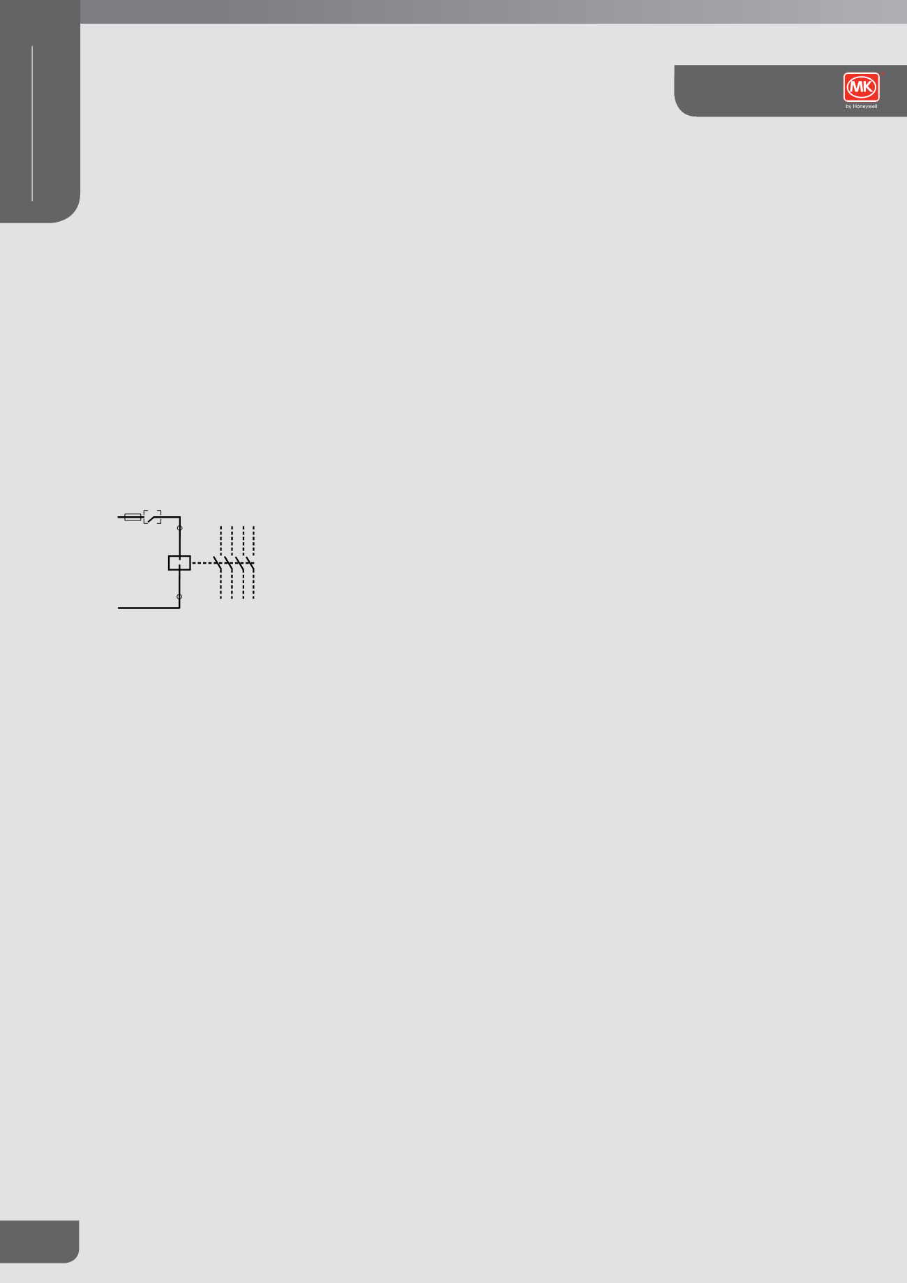
Typical schematic layouts of modular contactors
Without Manual Override
1 3
4
5
6 8
7
2
L
1 3
4
5
6 8
7
2
N
A1
A2
Contactors