
7
Switch Disconnectors
8UC7 Door-Coupling Rotary Operating Mechanisms
For 3K switch disconnectors
7/85
Siemens LV 10 · 2014
■
Application
8UC7 door-coupling rotary operating mechanisms can be used
in electrical controls, distribution boards and switchgear in
cases where switches have to be mounted behind covers, end
plates and doors that must be opened and where they are to be
operated manually from outside.
Interlocking conditions
The basic versions of the rotary operating mechanisms comply
with the following interlocking conditions:
• Operating mechanism and switching device in "0" (OFF) posi-
tion: The control cabinet door can be opened. With padlocks
fitted, the control cabinet door remains locked however.
• Operating mechanism and switching device in "I" (ON) posi-
tion: The control cabinet door cannot be opened in this posi-
tion. However, the interlock can be overridden and the control
cabinet door opened by trained personnel for performing
checks. No padlocks can be fitted in "I" position.
Other interlocking conditions:
• If no door interlock is required, the user can remove the door
interlocking plate of the rotary operating mechanism.
• It is easy for the user to fit padlocks to the rotary operating
mechanisms in the "I" position as well. In this case the door
cannot be opened, the operating mechanism cannot be actu-
ated and the door interlock cannot be overridden.
Operating conditions and ambient conditions
The temperature range for operation of the rotary operating
mechanisms is between -25 °C and +60 °C.
Thanks to the use of glass fiber-reinforced molded plastic for
handles and masking plates as well as metal components with
surface protection, the rotary operating mechanisms are suit-
able for rough conditions, high air humidity and aggressive
atmospheres.
■
Design
Components
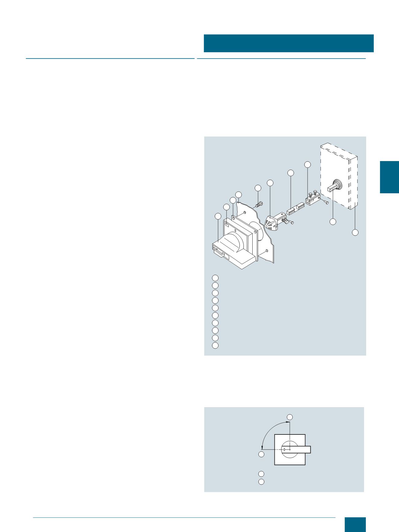
The rotary operating mechanisms consist of a masking plate
with handle, including seal and fixing screws for door installa-
tion, an extension shaft (300 mm) and a coupling driver to be
mounted onto the switch shaft.
Operating mechanisms for 3KA / 3KL / 3KM switch disconnec-
tors do not have a shaft coupling since the extension shaft is
fitted directly into the switch. Extension shafts with a length of
600 mm are also available.
Design, schematic representation
Switch position
In order to ensure compliance with locking and interlocking con-
ditions, the controls and operating mechanisms must be in-
stalled such that, with two-position switches the "0" position lies
at 9 o'clock and the "I" position at 12 o'clock.
Positions for two-position switches with 90° operating angle
Handle with masking frame
Seal
Door
Fixing screws
Coupling driver
Extension shaft
Adapter
Operating shaft of switching device
Switching device
Tripped plate (can be glued on if required)
NSE0_00022a
1
2
3
4
5
6
7
8
9
10
1
2
3
4
5
6
7
8
9
10
90°
0°
NSE0_00352
1
1
2
2
o'clock position
o'clock position
12
9
© Siemens AG 2014


