
Switch Disconnectors
8UC7 Door-Coupling Rotary Operating Mechanisms
For 3K switch disconnectors
7/84
Siemens LV 10 · 2014
7
■
Overview
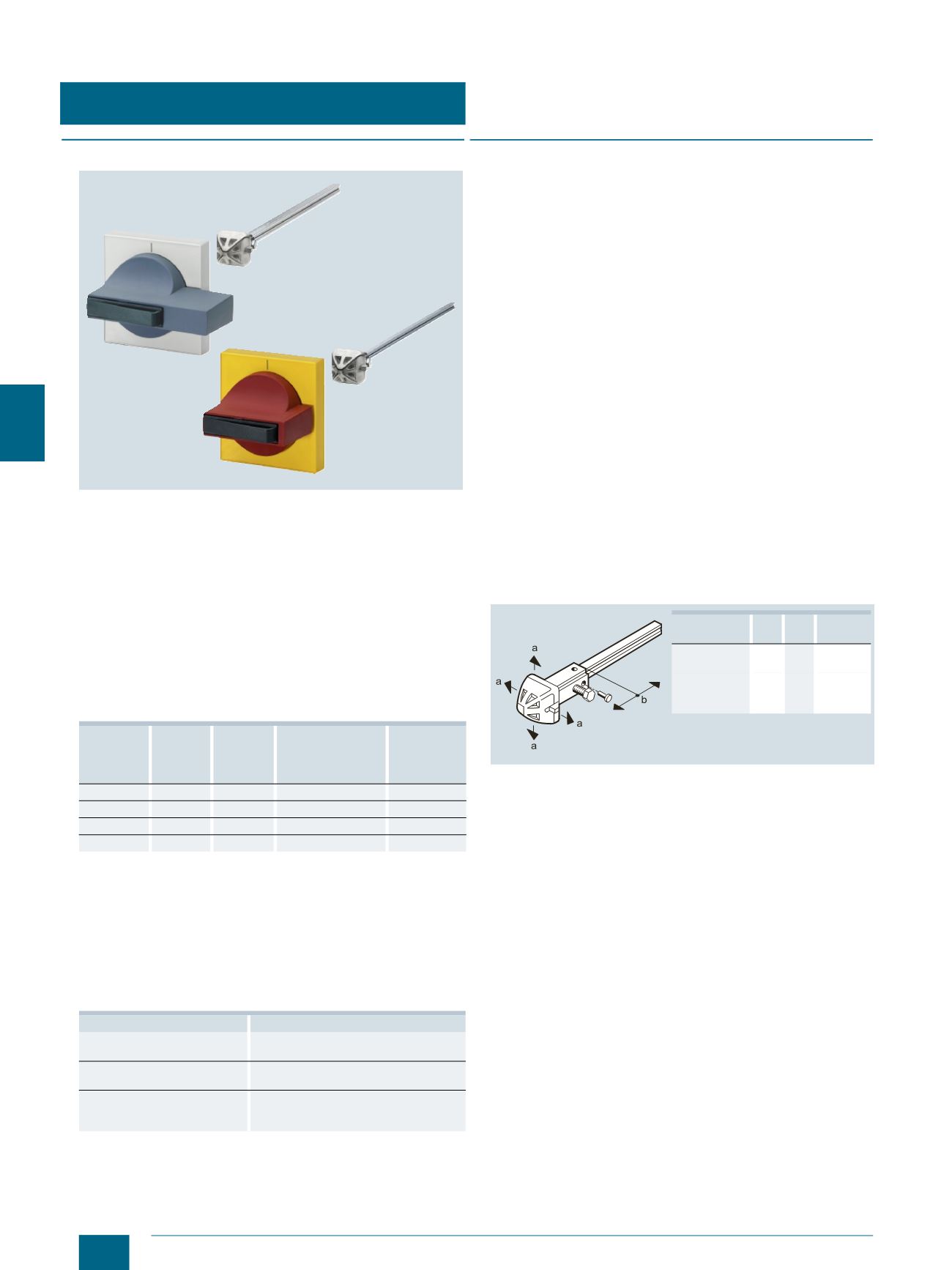
8UC7 rotary operating mechanism in STANDARD version (left) and
EMERGENCY-STOP version (right)
With door-coupling rotary operating mechanisms it is also possi-
ble to operate switch disconnectors from the outside with the
control cabinet doors closed.
The rotary operating mechanisms are available in "STANDARD"
and "EMERGENCY-STOP" versions with the following differ-
ences:
• STANDARD version: Masking plates in light-gray
with black inscription, handles in ti-grey
• EMERGENCY-STOP version: Masking plates in yellow
with black inscription, handles in red
Available sizes
1)
Operating mechanisms tested with triple torque (according to
EN 60947-3). They are therefore also suitable for applications in this area.
2)
Operation with two hands.
Degree of protection
Degree of protection when installed is IP65.
Standards
8UC7 door-coupling rotary operating mechanisms are in line
with for example the following standards:
■
Benefits
Can be locked
The retractable locking device integrated in the handles is suit-
able for padlocks with shackle diameters of 4.5 mm to 8.5 mm
(locks according to DIN 7465).
Up to three padlocks with a shackle diameter of 8.5 mm and up
to five padlocks with a shackle diameter of 6 mm can be fitted
simultaneously.
Non-interchangeability
In order to ensure that, when installing switches and door-cou-
pling operating mechanisms, all components are assembled in
the correct position with respect to one another, the components
are provided with non-interchangeability features (rivel and lug).
Stops
Stops are used to prevent damage occurring as the result of ex-
cessive torque. These stops are supplied loose with the rotary
operating mechanisms and can be fitted as required. Stops are
fitted at the factory to size 1 and 2 rotary operating mechanisms
with a 90° operating angle (exception: 3RV motor starter protec-
tors/circuit breakers).
Tolerance compensation
8UC7 rotary operating mechanisms are capable of taking up a
radial eccentricity of max. 3 mm between the actuating shaft of
the switching device and the door-coupling rotary operating
mechanism. Supporting the extension shaft is recommended
with greater tolerances.
Permissible radial eccentricity and axial tolerance compensation in mm
Pull-out strength
The pull-out strength of interlocked operating mechanisms, e.g. pulling
off the shaft or destruction of the operating mechanism, amounts to 800 N
when the pulling force acts directly onto the operating mechanism in di-
rection of shaft.
Rotary
operating
mechanisms
Size
Rated
torque
1)
Shaft profile
Masking plate
Nm mm x mm
mm x mm
8UC71
1
4
6 x 6
75 x 75
8UC72
2
9
8 x 8
75 x 75
8UC73
3
25
10 x 10 or 12 x 12 100 x 100
8UC74
4
40/55
2)
12 x 12
100 x 100
Standard
Title
IEC 60204-1, EN 60204-1
(VDE 0113 Part 1)
Safety of machinery; electrical equipment
of machines
IEC 60439-1, EN 60439-1
(VDE 0660 Part 500)
Low-voltage switchgear and controlgear
assemblies
IEC 60947-3, EN 60947-3
(VDE 0660 Part 107)
Low-voltage switchgear and controlgear;
Switches, disconnectors, switch discon-
nectors and fuse-combination units
NSE0_00945a
Coupling
drivers
a b Shaft
length
With tolerance
compensation
+3
5 x
Without
tolerance
compensation
+1.5
2.5 x+23.5
© Siemens AG 2014


