


 464 / 582

BETA Monitoring
Monitoring of Electrical Values
5
TT3 voltage relays
13/8
Siemens ET B1 · 10/2008
13
■
Schematics
l
5
TT3 411 and 5TT3 412 voltage relays
For schematics of the 5TT3 411 and 5TT3 412 voltage relays,
see
"
Monitoring of medical premises" on page 13/32.
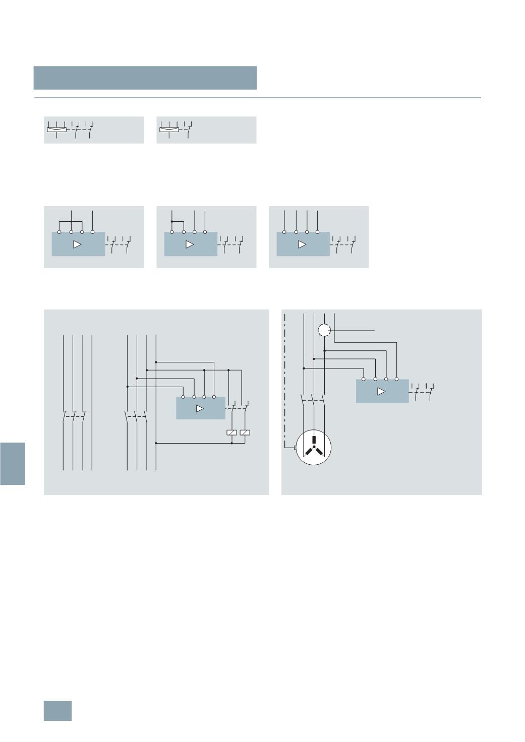
Switching example for
5
TT3 195, 5TT3 40 voltage relays
1, 2, 3-
phase operation against N
5
TT3 194
5
TT3 195
5
TT3 402
5
TT3 403
5
TT3 404
5
TT3 405
5
TT3 406
5
TT3 407
5
TT3 408
5
TT3 410
5
TT3 400
5
TT3 401
11
12 14
21
22 24
L3 L2 L1
N
11
12 14
L3 L2 L1
N
14 12 24 22
11 21
I2_07594c
L1 L2 L3 N
L1 N
One-phase operation
14 12 24 22
11 21
I2_07595c
L1 L2 L3 N
L1
L2
Two-phase operation
14 12 24 22
11 21
I2_07596c
L1 L2 L3 N
L1
L3 L4
L2
Three-phase operation
Switching example for
5
TT3 401, 5TT3 403, 5TT3 405 undervoltage relays
Switching example for
5
TT3 404, 5TT3 405, 5TT3 406, 5TT3 408 undervoltage relays
One application of the undervoltage relays is the switchover to a safety power
supply after a fault.
Buildings are distinguished according to use, such as business premises,
exhibition areas or guest houses. These are all covered generically as
rooms/buildings where "people meet".
There is a fault if the voltage of the general power supply drops > 15 % in relation
to the rated voltage for 0.5 seconds (i.e. 195 V at 230 V).
In this case, depending on the type of use of the building, the lighting must be
switched to a safety power supply after 0.5 to 15 s. A safety power supply may
be: a battery system, generating set or a quick-starting standby generating set.
These voltage relays can only be used for 3-phase operation. As well as
monitoring undervoltages and overvoltages in accordance with their
description, they also monitor reverse voltage, asymmetry and
N-conductor breaks.
14 12 24 22
11 21
L1' L2' L3' N'
I2_07272d
L1 L2 L3 L4
K2
L1 L2 L3 N
K1
K1
K2
Emergency
power supply
Standard
power supply
Emergency
lighting
Standard
lighting
3 230
V AC
I2_07273d
L1 L2 L3 N
L1 L2 L3 N
K1
1412 24 22
11 21
M
PE
Phase failure
© Siemens AG 2008