


 394 / 582

BETA Switching
Timers
7
LF6, 5TT1 3 timers for buildings
9/16
Siemens ET B1 · 10/2008
9
■
Overview
Stairwell lighting is part of the standard equipment of a building.
This is required in DIN 18015-2 "Electrical systems in residential
buildings; minimum type and scope of equipment".
Stairwell lighting timers can be distinguished by the level of
convenience offered with regard to the range of functions. The
required time can be precisely set using the push-to-lock knurling
wheel setting. With modern four-wire installations, stairwell lighting
timers can always just be pressed again. A maintained light
switch prevents the need for repeated pressing, for example
during relocations.
■
Benefits
•
Reliable durable switching of incandescent lamps using patented
contact design
•
Ultra-quiet stairwell lighting timers – ideal for residential areas
•
Energy savings through disconnection of unnecessary
equipment
•
Warning prior to switch off acc. to DIN 18015-2 for stairwell
lighting in apartment houses.
■
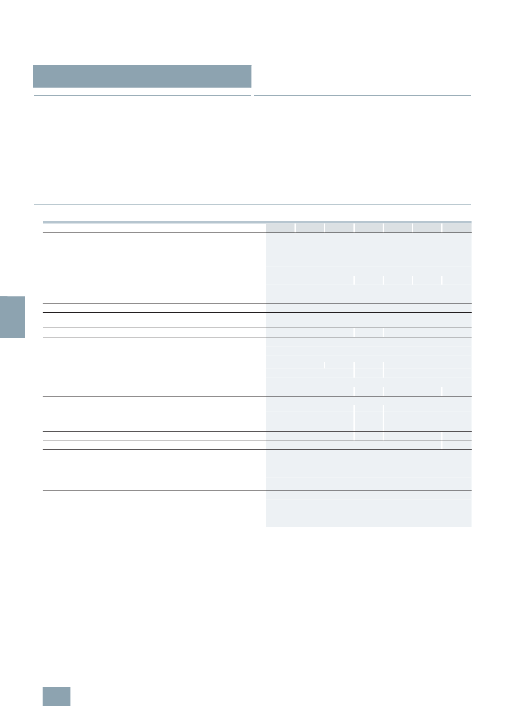
Technical specifications
7
LF6 110 7LF6 111 7LF6 113 5TT1 303 7LF6 114 7LF6 115 7LF6 112
Standards
IEC 60669, EN 60669
Supply
•
Rated control supply voltage U
c
V AC
230
-
Operating range
At 50/60 Hz
×
U
c
0.9 ... 1.1
•
Rated power dissipation P
v
VA
Approx. 5
Setting ranges
min
0.5 ... 10
1 ... 10 0.5 ... 10 3 ... 60 0.5 ... 10
•
Accuracy
s
±30
Manual switches
Automatic/permanent
Yes
Minimum push duration
ms
30
Voltage endurance
At pushbutton input
(
pushbutton malfunction)
Yes
Short-circuit strength
A
700
--
700
Channels/contacts
•
Switching channels
-
Rated operational voltage U
e
V AC 250
-
Rated operational current
I
e
At p.f. = 1
A
16
--
10
16
•
Contact gap
mm > 3
0.3
> 3
•
Minimum contact load
V; mA 10; 300
Max. incandescent lamp load
W 2000
--
2000
--
Fluorescent lamp load 58 W
-
Uncorrected
Unit(s)
20
--
20
-
DUO circuit
Unit(s)
2
× 20
--
2
× 20
-
Siemens ECG
1
lamp
Unit(s)
10
6
10
2
lamps
Unit(s)
2
× 5
3
2
× 5
Glow lamp load
mA
50
10
50
--
Max. fan load
VA
--
200
Terminals
•
Terminals ± screw (Pozidriv)
PZ 1
•
Conductor cross-sections of main current paths
-
Rigid
mm
2
1.5 ... 6
-
Flexible, with end sleeve
Min.
mm
2
1
Environmental conditions
•
Permissible ambient temperature
°C
-10 ...
+50
•
Resistance to climate
Acc. to EN 60068-1
20/045/04
•
Degree of protection
Acc. to EN 60529
IP20, with connected conductors
© Siemens AG 2008