


 324 / 582

BETA Switching
Switches and Light Indicators
5
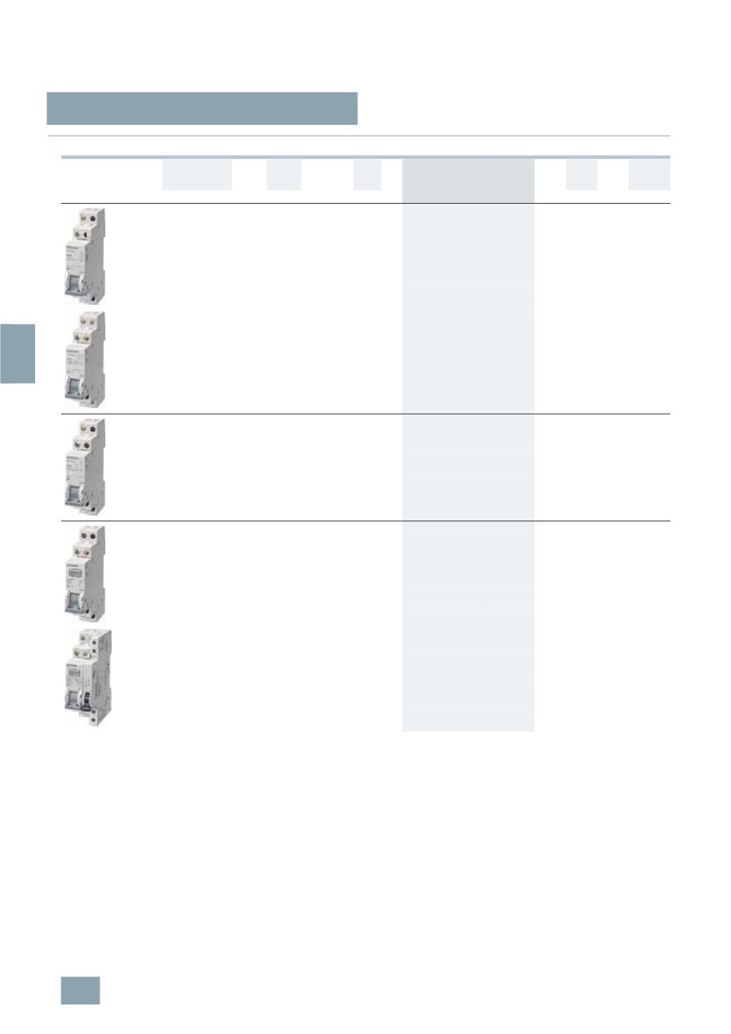
TE8 control switches
7/4
Siemens ET B1 · 10/2008
*
You can order this quantity or a multiple thereof.
7
■
Selection and ordering data
Version
I
e
U
e
Conductor
cross-
sections
MW DT Order No.
Price
per PU
PG PU PS*/
P. unit
Weight
per PU
approx.
A
V AC Up to mm
2
Unit(s) Unit(s) kg
Two-way switches (20 A)
With sealable switch position,
separate handle locking device can be retrofitted
Mountable auxiliary switch
1
NO + 1 NC 20
400 6
1
}
5
TE8 151
027 1
1
0.062
Auxiliary switch cannot be retrofitted
2
NO + 2 NC 20
400 6
1
B
5
TE8 152
027 1
1
0.081
3
NO + 1 NC 20
400 6
1
B
5
TE8 153
027 1
1
0.082
1
CO
20
230 6
1
}
5
TE8 161
027 1
1
0.060
2
CO
20
400 6
1
}
5
TE8 162
027 1
1
0.076
Group switches with center position (20 A)
With sealable switch position,
separate handle locking device can be retrofitted
Auxiliary switch cannot be retrofitted
1
CO contact
20
230 6
1
}
5
TE8 141
027 1
1
0.060
2
CO contacts 20
400 6
1
}
5
TE8 142
027 1
1
0.077
Control switches (20 A)
With fixed mounted glow lamp 230 V or diode 48 V,
with replaceable, white transparent luminescent cap,
with sealable switch position separate handle locking
device can be retrofitted
Auxiliary switch cannot be retrofitted
1
NO
20
230 6
1
}
5
TE8 101
027 1
1
0.057
20
48 6
1
B
5
TE8 101-3
027 1
1
0.057
1
NO, for max.
150
m cable
length
20
230 6
1
B
5
TE8 105
027 1
1
0.057
2
NO
20
400 6
1
B
5
TE8 102
027 1
1
0.066
3
NO
20
400 6
1
B
5
TE8 103
027 1
1
0.078
With mounted auxiliary switch (1 NO, 1 NC)
3
NO
20
400 6
1.5
B
5
TE8 108
027 1
1
0.128
© Siemens AG 2008