


 323 / 582

BETA Switching
Switches and Light Indicators
5
TE8 control switches
7/3
Siemens ET B1 · 10/2008
7
*
You can order this quantity or a multiple thereof.
■
Overview
Two-way switches are used in control cabinets and distribution
boards for switching small loads on/off or over.
Group switches with center position permit the positions
open/stop/closed, for example to control anti-clockwise rotation
-
Off - clockwise rotation.
Control switches in a range of contact versions have an integral
control lamp for the ON setting.
The auxiliary switch (AS) signals the contact position of the switch.
It has the same design as the auxiliary switch used for the miniature
circuit breakers
(
see Chapter "Miniature Circuit Breakers")
.
■
Benefits
•
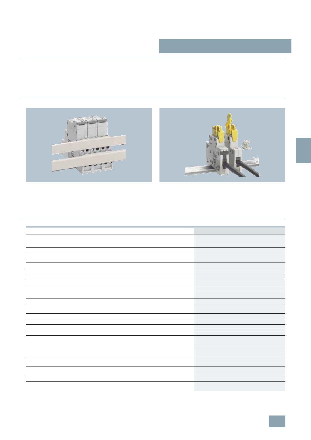
The control switches can be bus-mounted with each other or with
5
TE4 8 pushbuttons, 5TE5 8 light indicators or 5TT4 1 remote
control switches and 5TT4 2 switching relays. This saves time
and space.
•
For busbars, see page
see page 7/22 ff
.
•
The handle locking device prevents undesired manual on and
off switching. This increases safe operation.
•
The handle locking device is a universal accessory for all
switches and miniature circuit breakers. This simplifies logistics.
■
Technical specifications
.
5
TE8 1
Standards
IEC/EN 60947-3 (VDE 0660-107);
IEC/EN 60669-1 (VDE 0632-1)
Approved acc. to
EN 60669
Rated operational current
I
e
Per conducting path
A
20
Rated operational voltage U
e
1-
pole
V AC 230
Multipole
V AC 400
Rated power dissipation P
v
Contact per pole
VA
0.7
Thermal rated current
I
the
A
20
Rated breaking capacity
At p.f. = 0.65
A
60
Rated making capacity
At p.f. = 0.65
A
60
Short-circuit strength
In conjunction with fuse of the same
rated operational current
EN 60269 gL/gG
kA
10
Rated impulse withstand voltage U
imp
kV
> 5
Clearances
Open contacts
mm 2 × > 2
Between the poles
mm > 7
Creepage distances
mm > 7
Mechanical service life
Switching cycles
25000
Electrical service life
Switching cycles
10000
Minimum contact load
V; mA 10; 300
Rated short-time currents
Per conducting path at p.f. = 0.7
Up to 0.2 s
A
650
Up to 0.5 s
A
400
(
The respective rated surge current can
Up to 1 s
A
290
Calculated by multiplying by a factor of 1.5).
Up to 3 s
A
170
Terminals
± screw (Pozidriv)
1
Max. tightening torque
Nm 1.2
Conductor cross-sections
Rigid
mm
2
1.5 ... 6
Flexible, with end sleeve
mm
2
1 ... 6
Permissible ambient temperature
°C
-5 ...
+40
Resistance to climate
At 95 % relative humidity
Acc. to DIN 50015
°C
45
© Siemens AG 2008