


 319 / 582

BETA Protecting
Overvoltage Protection Devices
Surge arresters for
measuring and control technology
6/33
Siemens ET B1 · 10/2008
6
*
You can order this quantity or a multiple thereof.
Combination options for basic elements and male connectors
■
Selection and ordering data
Male connector
Basic element
5
SD7 502-0
5
SD7 520-1
5
SD7 522-7
5
SD7 530-3
5
SD7 541-7
5
SD7 550-4
5
SD7 500-0
✓
--
--
--
--
--
5
SD7 512-1
--
✓
--
✓
--
--
5
SD7 522-0
--
--
✓
--
--
✓
5
SD7 522-1
--
--
✓
--
--
✓
5
SD7 541-1
--
--
--
--
✓
--
Version
Rated arrester
voltage U
C
MW DT Order No.
Price
per PU
PG PU PS*/
P. unit
Weight
per PU
approx.
V AC V DC
Unit(s) Unit(s) kg
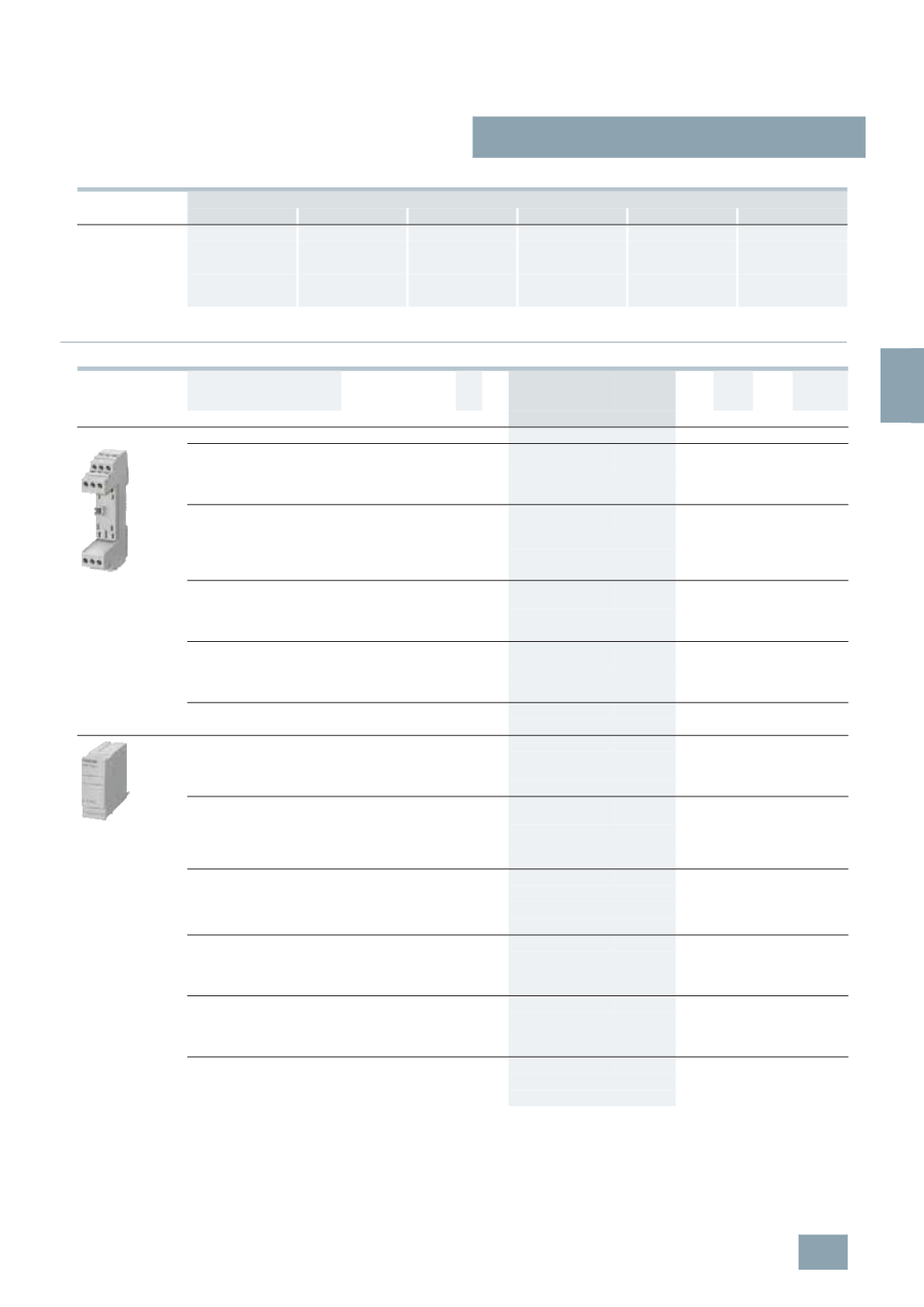
Basic elements
•
For male connectors with protection circuit for one
2-
wire ungrounded signal circuit
1
B
5
SD7 512-1
008 1
1
0.050
•
Jumper between terminals 3/4 (GND) and 9/10
•
For 5SD7 520-1 and 5SD7 530-1 male connectors
•
For male connectors with protection circuit for two
2-
wire ungrounded signal circuits
1
B
5
SD7 522-1
008 1
1
0.056
•
Jumper between terminals 3/4 (GND) and 9/10
•
For 5SD7 522-1 and 5SD7 550-4 male connectors
•
For male connectors with protection circuit for two
2-
wire ungrounded signal circuits
1
B
5
SD7 522-0
008 1
1
0.057
•
Gas arrester between terminals 3/4 (GND) and 9/10
•
For 5SD7 522-1 and 5SD7 550-4 male connectors
•
For male connectors with protection circuit for four
conductors single-sided grounded signal circuit
1
B
5
SD7 541-1
008 1
1
0.056
•
Jumper between terminals 3/4 (GND) and 9/10
•
For 5SD7 541-7 male connectors
•
Jumper between terminals 3/4 (GND) and 9/10
1
B
5
SD7 500-0
008 1
1
0.050
•
For 5SD7 502-0 male connectors
PROFIBUS male connectors
1
B
5
SD7 530-3
008 1
1
0.020
•
Protection for 2 signal cores with shared reference
potential
•
For 5SD7 512-1 basic element
Male connectors for analog telecommunication
interfaces
1
B
5
SD7 520-1
008 1
1
0.020
•
Protection for 2-wire Telecom cable
(
U
k0
or T-DSL)
•
For 5SD7 512-1 basic element
Male connectors, 24 V AC
1
B
5
SD7 522-7
008 1
1
0.024
•
Protection for two 2-wire ungrounded signal circuits.
•
Fine protection element between the respective wires
•
For 5SD7 522-0 and 5SD7 522-1 basic elements
Male connectors, 12 V DC
1
B
5
SD7 550-4
008 1
1
0.026
•
Protection for field bus systems and signal circuits in
3-
or 4-wire method
•
For 5SD7 522-0 and 5SD7 522-1 basic elements
Male connectors, 24 V DC
1
B
5
SD7 541-7
008 1
1
0.026
•
Protection for 4 signal cores with shared reference
potential
•
For 5SD7 541-1 basic element
Male connectors, 2-wire
1
B
5
SD7 502-0
008 1
1
0.020
•
Coarse protection for 2 single-sided signal leads
•
For 5SD7 500-0 basic element
N
© Siemens AG 2008