


 320 / 582

BETA Protecting
Overvoltage Protection Devices
Surge arresters for
measuring and control technology
6/34
Siemens ET B1 · 10/2008
6
*
You can order this quantity or a multiple thereof.
■
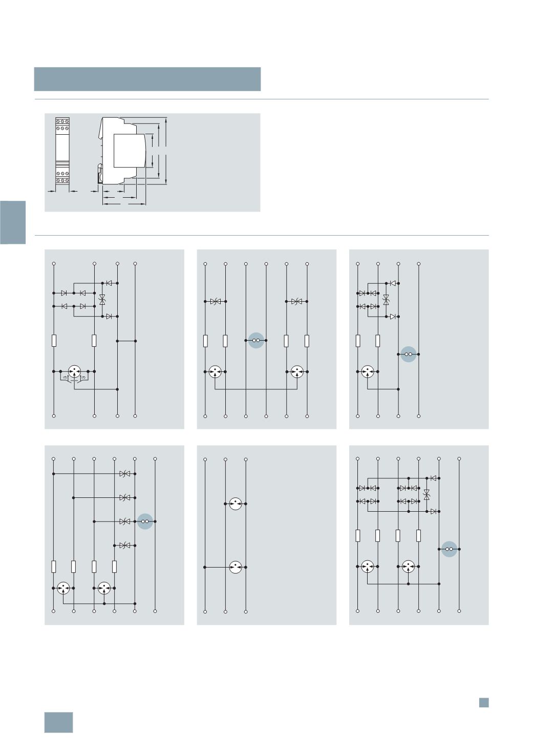
Dimensional drawings
■
Schematics
1)
With the 5SD7 512-1, 5SD7 522-1, 5SD7 541-1 and 5SD7 500-0 basic
elements , the terminals 9 and 10 (GND) directly linked to the standard
mounting rail over the metallic mounting foot.
2)
With the 5SD7 522-0 basic element, the terminals 9 and 10 (GND) are
linked with the metallic mounting foot over a gas arrester.
5
SD7 5..
5
SD7 520-1
5
SD7 522-7
5
SD7 530-3
5
SD7 541-7
5
SD7 502-0
5
SD7 550-4
I2_15520
18
7 9 11
8 1012
45
71
90
45
29 7
59
11
3 9
7
8
12 10 4
I2_15523
PE
PE
IN
OUT
11
7
3
1) 2)
5 1
2
8
6
12
10
9
4
I2_15524
PE
PE
IN
OUT
9 11
7
8 12 10
3
4
I2_15525
1)
PE
PE
IN
OUT
11 9
7 5 1
2
8 6
12 10
3
4
I2_15526
1)
PE
PE
IN
OUT
5 3
1
6 2
4
I2_15521
PE
PE
IN
OUT
11 9
7 5 1
2
8 6
12 10
3
4
I2_15522
1) 2)
PE
PE
IN
OUT
© Siemens AG 2008